
Method for indirect tire pressure monitoring and tire pressure monitoring system

a technology of tire pressure monitoring and monitoring system, which is applied in the direction of instruments, structural/machine measurement, transportation and packaging, etc., can solve the problems of increasing tire wear and fuel consumption, tire defect, eigen frequency or resonant frequency varies, etc., to achieve more reliable warning, reduce computation complexity and/or memory space, and be convenient to carry out

Inactive Publication Date: 2010-08-19
CONTINENTAL TEVES AG & CO OHG
View PDF4 Cites 11 Cited by
  • Summary
  • Abstract
  • Description
  • Claims
  • Application Information

AI Technical Summary

Benefits of technology

[0013]According to one preferred embodiment of the method according to aspects of the invention, the characteristic variable is taken into account by using the characteristic variable to correct the pressure loss identification variable. The disturbance influences contained in the characteristic variable are calculated out of the pressure loss identification variable in this way. A warning is then produced on the basis of the corrected, undisturbed pressure loss identification variable, thus very largely avoiding spurious warnings.
[0031]One advantage of the method according to aspects of the invention is that it allows reliable, wheel-specific tire pressure loss monitoring. Influences of disturbance variables on the pressure loss identification are minimized.

Problems solved by technology

By way of example, an abnormal tire air pressure can increase the tire wear and the fuel consumption, and can lead to a tire defect (“tire bursting”).
However, the eigen frequency or resonant frequency varies not only as a result of a change in the tire pressure but also as a result of further disturbance variables.
If these influences are ignored, this can lead to spurious warnings or else to correct warnings not being produced.

Method used


Image

  • Method for indirect tire pressure monitoring and tire pressure monitoring system
  • Method for indirect tire pressure monitoring and tire pressure monitoring system
  • Method for indirect tire pressure monitoring and tire pressure monitoring system

Examples


Embodiment Construction

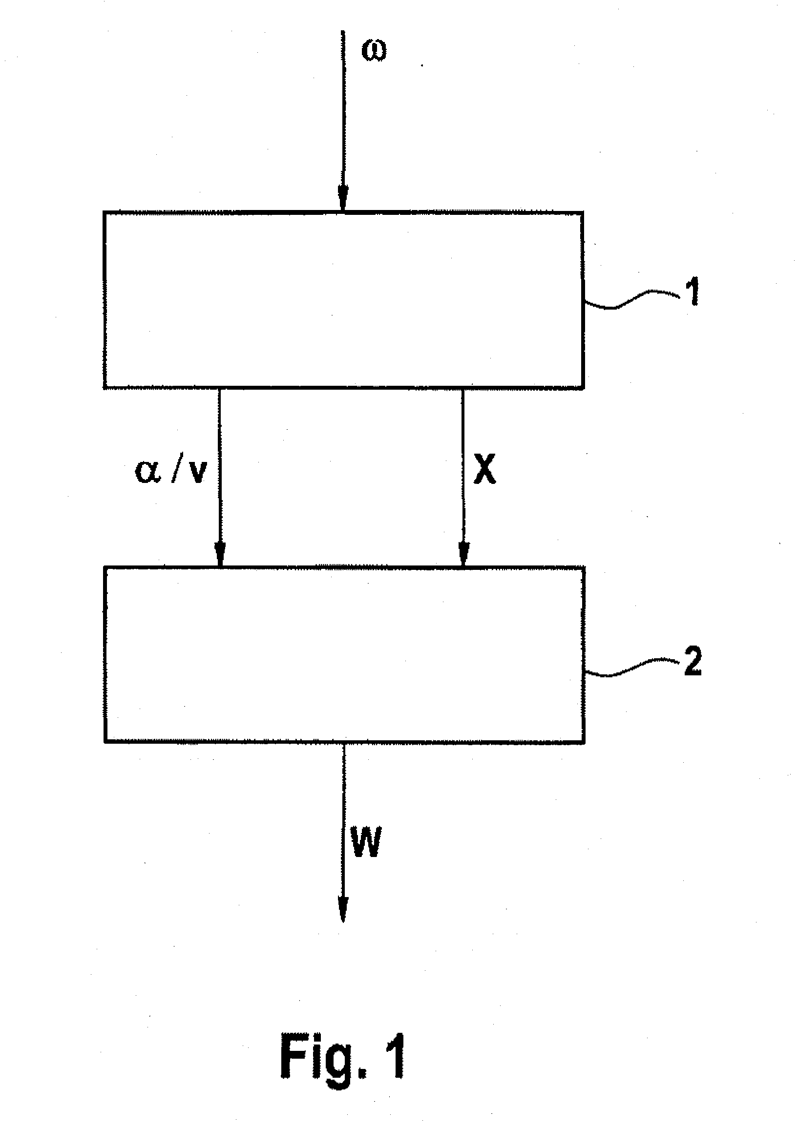
[0041]FIG. 1 shows, schematically, a flowchart of a first exemplary embodiment of a method according to aspects of the invention. An analysis of the oscillation behavior of the wheel is carried out in block 1, using a wheel rotation speed signal ω from a wheel. A characteristic variable α / v, which depends on a gradient α of a wheel torque slip curve and the vehicle speed v, and a pressure loss identification variable X are determined from the oscillation behavior of the wheel, in order to identify any pressure loss in the tire on the wheel. A check is then carried out in block 2, taking account of the characteristic variable α / v and on the basis of the pressure loss identification variable X, to determine whether any pressure loss has occurred. If a pressure loss is identified, then a warning W is emitted, for example to the driver.

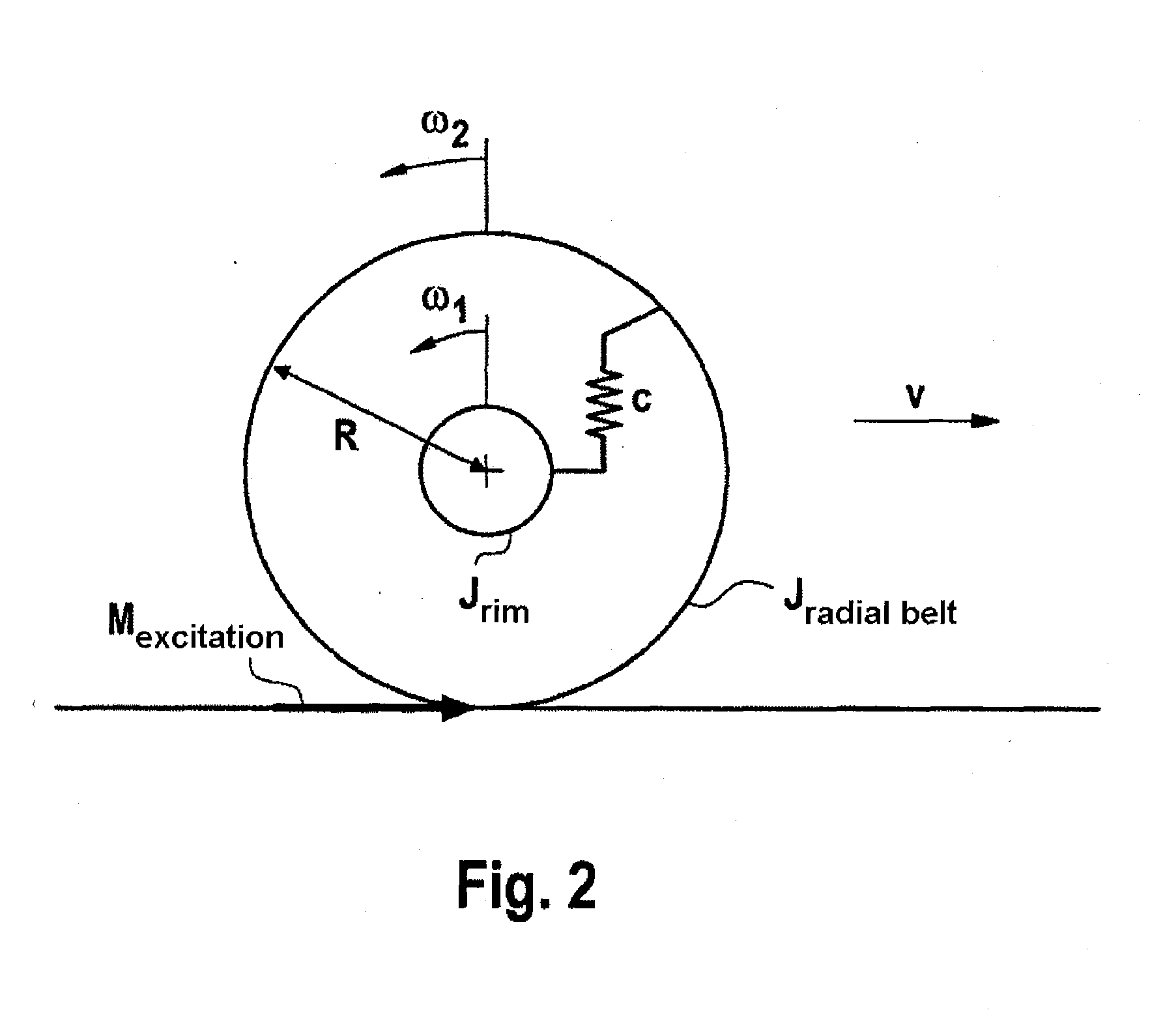
[0042]By way of example, the torsion eigen oscillation of the tire, which is dependent on the tire air pressure, is used for air pressure monitoring. Apa...


PUM


Abstract

A system and method for indirect tire pressure monitoring. A pressure loss variable (X, f, c) is determined based on an analysis of an oscillation behavior of a tire of a motor vehicle for the detection of a pressure loss in the tire of a wheel. A variable (α, α / v) representing an increase (α) of a wheel torque slip curve, or depending on an increase (α) of a wheel torque slip curve (α / v), is determined from the oscillation behavior of the tire, and the variable (α, α / v) and the pressure loss variable (X, f, c) are used for detecting the pressure loss.

Description

CROSS REFERENCE TO RELATED APPLICATIONS[0001]This application is the U.S. national phase application of PCT International Application No. PCT / EP2008 / 061486, filed Sep. 1, 2008, which claims priority to German Patent Application No. 10 2007 041 619.0, filed Sep. 3, 2007, and German Patent Application No. 10 2008 038 579.4, filed Aug. 20, 2008, the contents of such application being incorporated by reference herein.FIELD OF THE INVENTION[0002]The invention relates to a method for indirect tire pressure monitoring and to a tire pressure monitoring system.BACKGROUND OF THE INVENTION[0003]Modern motor vehicles are increasingly using systems which contribute to active or passive protection of the occupants. Systems for tire pressure monitoring protect the vehicle occupants against vehicle damage which is caused, for example, by an abnormal tire air pressure. By way of example, an abnormal tire air pressure can increase the tire wear and the fuel consumption, and can lead to a tire defect ...

Claims


Application Information

Patent Timeline
Patent Type & Authority Applications(United States)
IPC IPC(8): B60C23/00
CPCB60C23/062B60C23/061
Inventor FISCHER, DANIELIRTH, MARKUSKOBE, ANDREASSUSSMANN, CHRISTIAN
Owner CONTINENTAL TEVES AG & CO OHG
Learn More