
Drag minimizing projectile delivery system

a projectile and drag-minimizing technology, applied in the direction of firework flares/torches, smoke/mist generation, weapons, etc., can solve the problems of constant decrease of the velocity of the projectile, size and mass of the projectile, and the inability to simply scale up the cartridge of a shoulder-fired rifle and create a useable weapon for launching 40 mm grenades. , to achieve the effect of reducing the drag of the projectile bas

Inactive Publication Date: 2010-08-26
MARTIN ELECTRONICS
View PDF15 Cites 1 Cited by
  • Summary
  • Abstract
  • Description
  • Claims
  • Application Information

AI Technical Summary

Benefits of technology

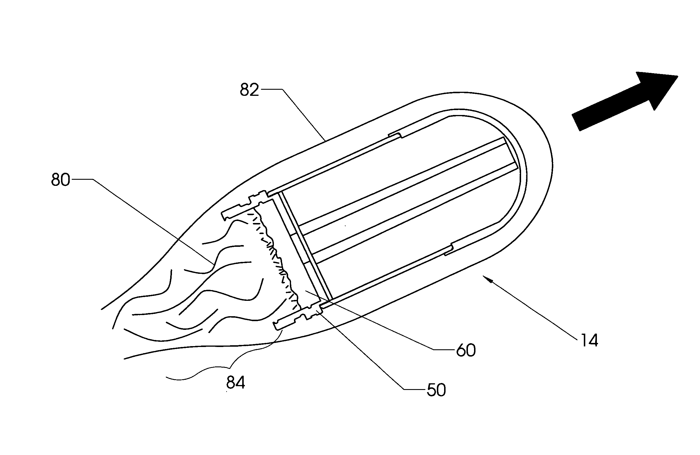
[0012]The present invention is a modified cartridge assembly including a projectile having a gas generator proximate its aft end. FIG. 1 shows cartridge assembly 10. Projectile assembly 14 is launched by propellant assembly 18. FIG. 4 shows projectile assembly 14 sectioned in half to show internal details. Aft closure 50 includes cavity 58, which is filled with gas generating material 66. Other ignition components are included as well. The gas generating material is ignited at or before the time the projectile exits the weapon's muzzle. The gas generating material then burns while the projectile is in flight, spewing pressurized gas into the wake region immediately behind the projectile. The pressurized gas reduces the projectile's base drag.

Problems solved by technology

The main difference, however, is the size and mass of the projectile.
Since the human operator can only withstand a fixed amount of recoil, one cannot merely scale up the cartridge of a shoulder-fired rifle and create a useable weapon for launching 40 mm grenades.
The velocity of the projectile diminishes continuously due to aerodynamic drag.

Method used


Image

  • Drag minimizing projectile delivery system
  • Drag minimizing projectile delivery system
  • Drag minimizing projectile delivery system

Examples


Embodiment Construction

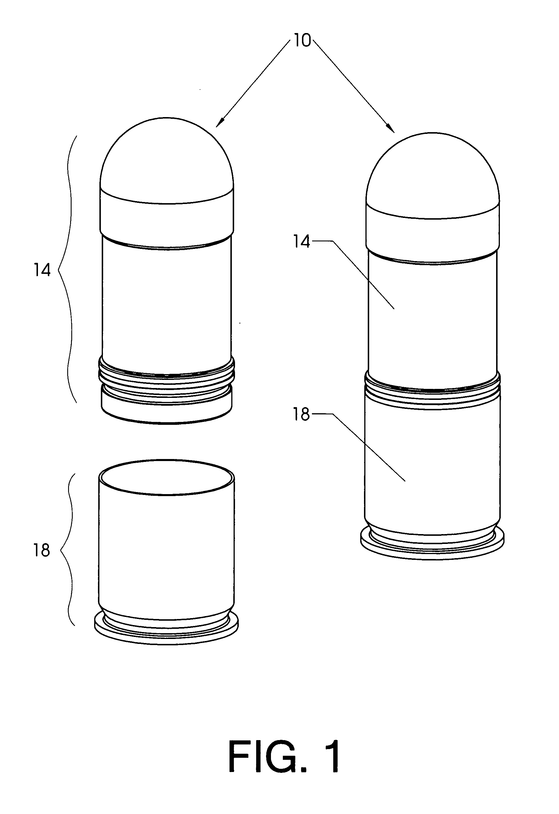
[0027]FIG. 1 shows the major components of a 40 mm cartridge assembly 10. Propellant assembly 18 has an open mouth at one end, into which projectile assembly 14 is inserted. The left hand view in FIG. 1 shows the propellant and projectile assemblies separated while the right hand view shows the two united.

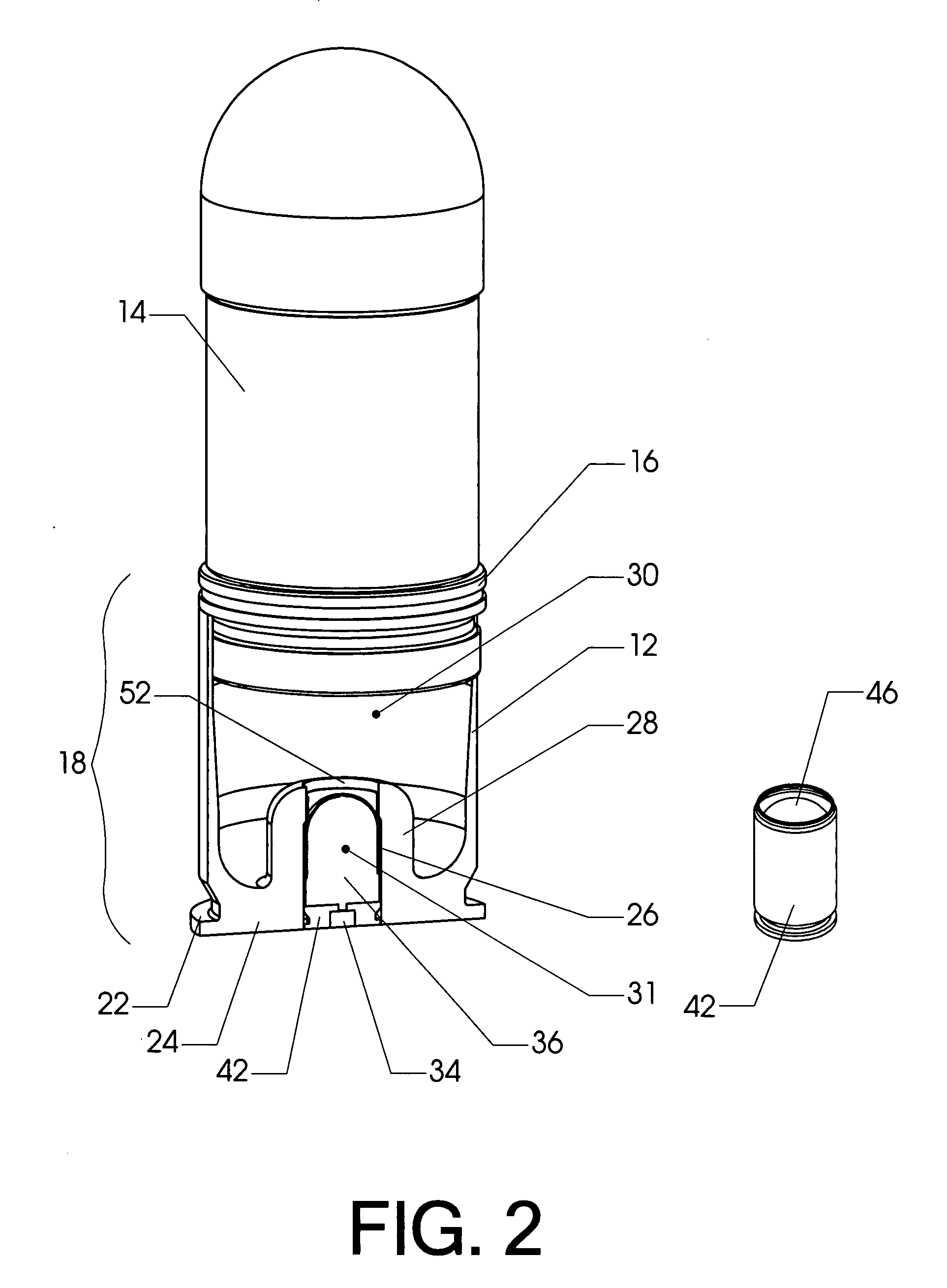
[0028]FIG. 2 shows the united cartridge assembly with the front half of propellant assembly 18 cut away to reveal internal details. The reader will observe that the aft portion (the lower portion in the orientation shown in the view) of the projectile assembly includes rifling ring 16. The rifling ring typically engages a rifled bore within a weapon designed to launch the projectile assembly. This engagement causes the projectile assembly to spin as it travels down the bore, thereby stabilizing it in flight.

[0029]Propellant assembly 18 is a high / low pressure launch system, as described more particularly in the incorporated U.S. Pat. No. 7,004,074 to Van Stratum (2006). High pressur...


PUM


Abstract

A modified cartridge assembly including a projectile having a gas generator proximate its aft end. The projectile includes an aft closure having a cavity filled with gas generating material. The gas generating material is ignited around the time the projectile exits the weapon's muzzle. The gas generating material then burns while the projectile is in flight, spewing pressurized gas into the wake region immediately behind the projectile. The pressurized gas reduces the projectile's base drag.

Description

CROSS-REFERENCES TO RELATED APPLICATIONS[0001]Not ApplicableSTATEMENT REGARDING FEDERALLY SPONSORED RESEARCH OR DEVELOPMENT[0002]Not Applicable.MICROFICHE APPENDIX[0003]Not ApplicableBACKGROUND OF THE INVENTION[0004]1. Field of the Invention[0005]This invention relates to the field of projectile delivery systems. More specifically, the invention comprises an improved projectile assembly having a gas generator in its aft end. The gas generator injects gas into the projectile's wake, thereby reducing the projectile's base drag.[0006]2. Description of the Related Art[0007]Although the present invention can be applied to many different types of projectiles, it was primarily developed as part of a propulsion system for launching 40 mm grenades (such as the U.S. Army's M433). The invention incorporates many features described in greater detail in prior U.S. Pat. No. 7,004,074 to Van Stratum (2006), which is hereby expressly incorporated by reference.[0008]Metallic cartridges have been use...

Claims


Application Information

Patent Timeline
IPC IPC(8): F42B10/38F42B12/48F42B4/26
CPCF42B10/40
Inventor VAN STRATUM, BRUCE G.
Owner MARTIN ELECTRONICS
Learn More