Sewing machine with detachable needle plate

Inactive Publication Date: 2010-08-26
BROTHER KOGYO KK
View PDF5 Cites 16 Cited by
  • Summary
  • Abstract
  • Description
  • Claims
  • Application Information

AI Technical Summary

Benefits of technology

[0008]Therefore, an object of the disclosure is to provide a sewing machine in which the fixing point of the needle plate on the bed can accurately be determined by a simpler work.

Problems solved by technology

However, a clearance between the needle hole and the needle is small since the needle hole is small as described above.
However, an adjusting work is troublesome in the above-described sewing machine.
Accordingly, although it may be suggested to determine the fixing point of the needle plate only by the tension screw and to fix the needle plate to the bed, it is difficult to accurately determine the fixing point of the needle plate on the bed since a clearance (an allowance) is generally provided between the tension screw (a male screw) and a female threaded screw hole (a female screw).

Method used


Image

  • Sewing machine with detachable needle plate
  • Sewing machine with detachable needle plate
  • Sewing machine with detachable needle plate

Examples


Embodiment Construction

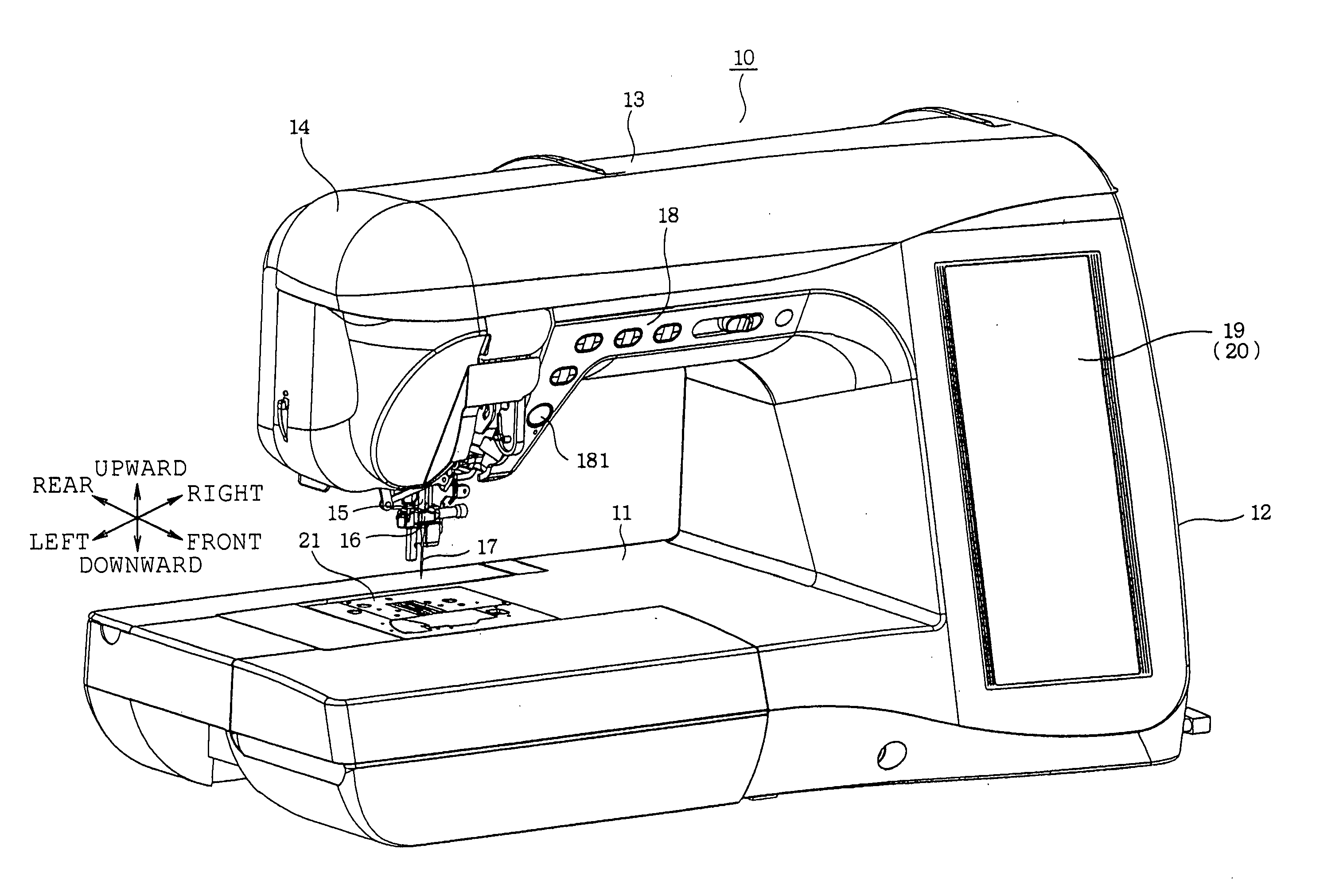
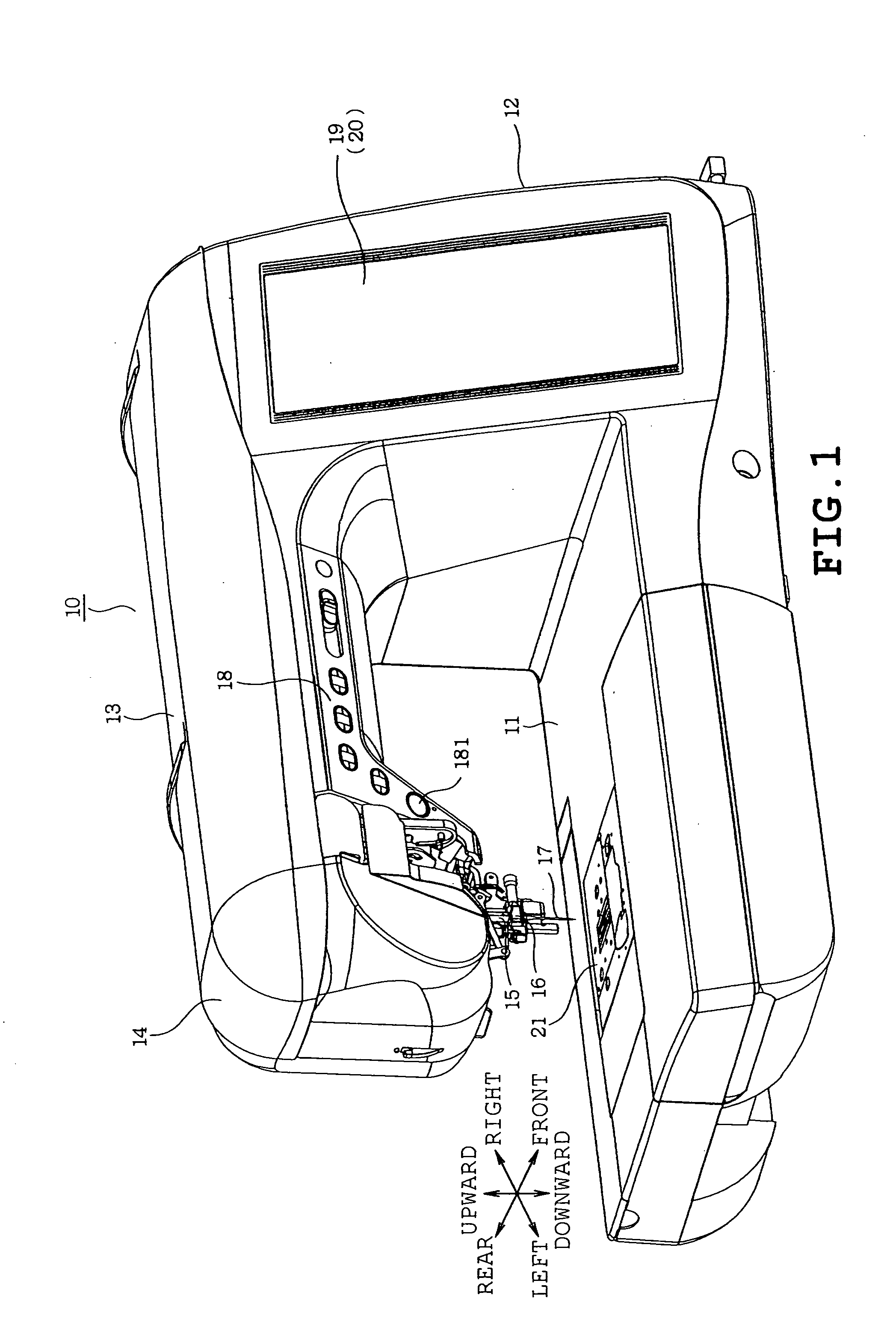
[0029]A first illustrative example which is applied to a household sewing machine will be described with reference to FIGS. 1 to 15C of the accompanying drawings in which front-back, right-left and up-down directions are shown by respective arrows.

[0030]Referring to FIG. 1, a sewing machine 10 includes a bed 11, a pillar 12 and an arm 13. The bed 11 is located at a lower end of the sewing machine 10 and extends horizontally. The pillar 12 stands upward on a right end of the bed 11. The arm 13 extends leftward from an upper end of the pillar 12. A sewing machine main shaft (not shown) extending in the right-left direction is housed in the arm 13. The arm 13 has a head 14 on a left end thereof. The head 14 is provided with a needle bar 15 and a needle thread take-up (not shown).

[0031]The main shaft is rotated by a sewing machine motor (not shown). When the main shaft is rotated, the needle bar 15 is moved up and down via a needle bar crank mechanism (not shown). Upon one turn of the m...


PUM


Abstract

A sewing machine includes a feed dog which transfers workpiece cloth, a needle plate having a first hole through which a needle is passed and a second hole through which a feed dog is movable upward and downward, a bed to which the needle plate is detachably attachable, a feeding mechanism which drives the feed dog in a front-back direction and in an up-down direction, an engaged portion formed in the needle plate, an engaging portion formed in the feed dog or the feeding mechanism, and a switching unit which switches the feed dog or the feeding mechanism between a transfer position where the feed dog transfers the workpiece cloth and a needle plate adjusting position which differs from the transfer position and where the engaging and engaged portions are engaged with each other thereby to determine a fixing point of the needle plate on the bed.

Description

CROSS-REFERENCE TO RELATED APPLICATIONS[0001]This application is based upon and claims the benefit of priority from the prior Japanese Patent Application No. 2009-43977 filed on Feb. 26, 2009, the entire contents of which are incorporated herein by reference.BACKGROUND[0002]1. Technical Field[0003]The present disclosure relates to a sewing machine provided with a needle plate detachably attachable to a bed thereof.[0004]2. Related Art[0005]A sewing machine includes a needle plate detachably attached to a bed thereof. The needle plate has a rectangular hole through which a feed dog is moved upward and downward so as to appear above and disappear below the needle plate and a needle hole through which a needle is passed. The rectangular hole is formed into such a size that the feed dog is movable therethrough. On the other hand, the needle hole is formed into such a size that a needle is passable therethrough during sewing, for example, in straight stitches or zigzag stitches. The need...

Claims


Application Information

Patent Timeline
IPC IPC(8): D05B73/12D05B27/00
CPCD05B73/12D05B27/02
Inventor MIZUNO, NOBORU
Owner BROTHER KOGYO KK
Why Eureka
Try Eureka