Tubular heat dispersing structure

a technology of heat dispersing structure and tubular structure, which is applied in the direction of tubular elements, lighting and heating apparatus, light sources, etc., can solve the problems of reducing the efficiency of heat dispersing in convection manner, baking phenomenon, etc., and achieves enhanced air convection, and improved heat dissipation efficiency

Inactive Publication Date: 2010-08-26
LI HONG TECHNOLOGICAL
View PDF6 Cites 9 Cited by
  • Summary
  • Abstract
  • Description
  • Claims
  • Application Information

AI Technical Summary

Benefits of technology

[0015]1. The tubular heat dispersing structure can have heat dispersing holes mounted thereon at positions of better air flowing, so as to enhance air convection.
[0016]2. The tubular heat dispersing structure can effectively guide the flowing of air, so as to reduce turbulence, thereby form an environment suitable for air convection.
[0017]3. The tubular heat dispersing structure can force the air to flow, which increases heat dispersing efficiency.
[0018]4. The tubular heat dispersing structure can be assembled for expansion in accordance with different heat dispersing demands, thereby enhancing the effect of heat dispersing.
[0019]5. The tubular heat dispersing structure can be varied according to the positions and shapes of the heat source(s) and the heat conductor to have different geometric shapes and sizes, and even, it can be assembled with the existing heat dispersing structure for improving the heat dispersing efficiency thereof.

Problems solved by technology

1. After air around the heat dispersing structure is heated, the density thereof will be changed, so as to cause disordered air flowing direction, thereby many disturbances and vortexes in small range form turbulence, which reduces the efficiency of heat dispersing in the convection manner.
2. The heat from the heat source and the heat conductor are transmitted to fins, and since fins have difficulty to disperse heat immediately, the heat dispersing structure oppositely will cause baking phenomenon.
3. The heat dispersing structure needs to employ external fan for producing airflow and increasing convection.
4. The heat dispersing structure has an open-up shape which can not be expanded by stacking or assembling.

Method used


Image

  • Tubular heat dispersing structure
  • Tubular heat dispersing structure
  • Tubular heat dispersing structure

Examples


Embodiment Construction

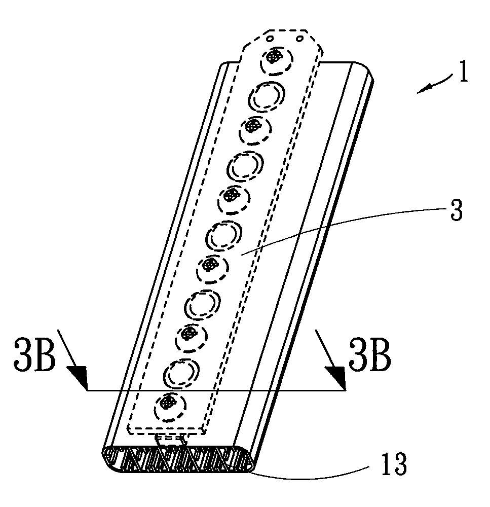
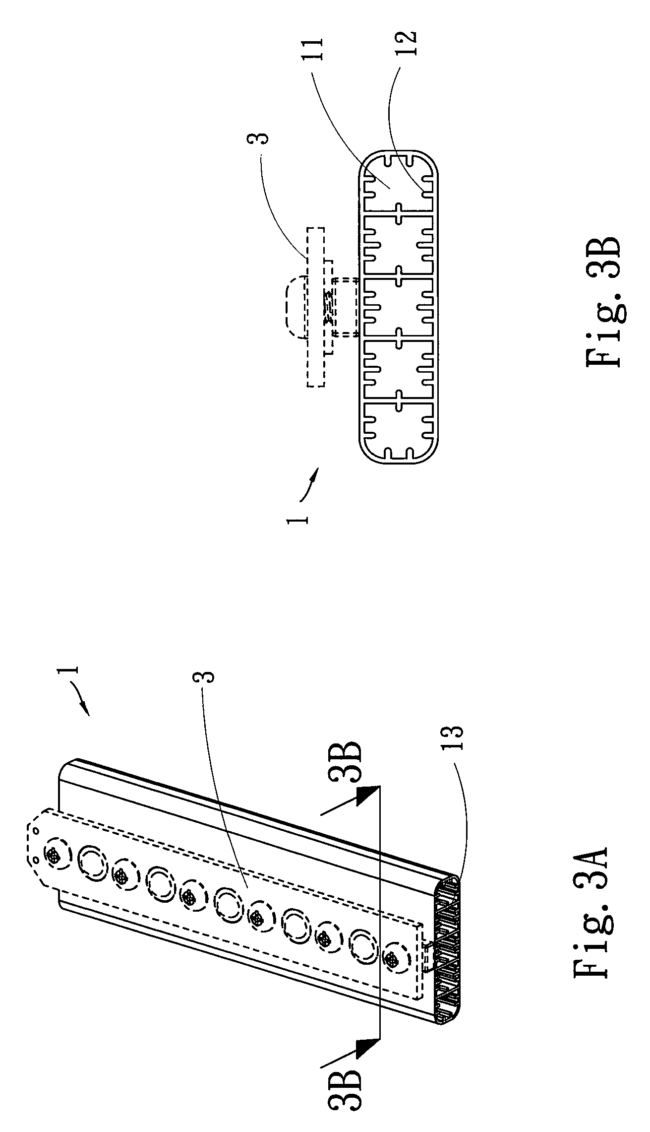
[0035]Please refer to FIGS. 3A, 3B, 4 and 5. When utilizing the tubular heat dispersing structure of the present invention, one or more heat sources and heat conductor 3 are attached to the outer circumference of the heat dispersing body 1, and through air convection, the heat from the heat sources and the heat conductor can be taken away. The present invention includes one or more heat dispersing body 1, which includes one or more channel 11 therein, wherein the channel 11 is a hollow tube with a section of closed geometric figure; plural fins 12 mounted on the inner surface of the channel 11 along the longitudinal direction of the channel 11; and openings 13 respectively mounted at two ends of the channel 11, so as to form the channel 11 passing through the heat dispersing body 1.

[0036]Please refer to FIG. 6 and FIG. 7. When using the tubular heat dispersing structure of the present invention, in accordance with the environment and airflow condition, the heat dispersing body 1 can...


PUM


Abstract

The present invention discloses a tubular heat dispersing structure which utilizes tubular channel to contact with the heat source(s) and the heat conductor for restricting the heated air. When the flowing air flows into the channel, it is to produce the flowing naturally, and the heated air flows toward the opening rapidly. Therefore, the structure of the present invention can form air flowing actively for achieving the heat dispersing effect. Besides, the structure of the present invention also can have varied geometric shapes and sizes for corresponding to different shapes of different heat sources and heat conductors, so that a better stacked attachment therebetween can be achieved, thereby saving the cost of building the molds and corresponding to the heat dispersing requirements of various power.

Description

FIELD OF THE INVENTION[0001]The present invention is related to a tubular heat dispersing structure, and more particularly to a tubular channel whose inner structure makes the air therein to produce airflow actively after being heated, so as to increase the effect of heat dispersing.BACKGROUND OF THE INVENTION[0002]There are three types of heat transmission, conduction, convection and radiation. Conduction utilizes medium to transmit heat from high temperature to low temperature, convection is formed by circular flowing of heated liquid (air or water) which is caused by density variation, and radiation can transmit heat without any medium.[0003]For liquid, the major and most effective manner to transmit heat is convention. Please refer to FIG. 1 and FIG. 2, the conventional heat dispersing structures 1a, 1b both employ conduction to perform heat dispersing, so that the structures thereof which have an open-up shape are formed to be similar to fins 11a, 11b or a variation thereof, th...

Claims


Application Information

Patent Timeline
Patent Type & Authority Applications(United States)
IPC IPC(8): F28F1/00
CPCF21K9/00F28F1/40F21K9/30F21Y2103/003F21V29/713F21V29/75F21V29/76F21V29/77F21V29/83F21V29/71F21K9/20F21Y2103/10F21Y2115/10
Inventor CHANG, KUN-JUNGJUAN, CHING-YUANLIN, KUO-CHUNJUAN, CHING-HUANG
Owner LI HONG TECHNOLOGICAL
Why Eureka
Try Eureka