Screen Flow Equalization System

a flow equalization and flow control technology, applied in the direction of sealing/packing, drilling pipes, borehole/well accessories, etc., can solve the problems of icds limiting the ability to circulate gravel packing slurries, other undesirable fluids, and limitations of the integrated design of screens with inflow control devices described, so as to facilitate further drilling, improve gravel deposition, and facilitate circulation

Inactive Publication Date: 2010-08-26
BAKER HUGHES INC
View PDF6 Cites 13 Cited by
  • Summary
  • Abstract
  • Description
  • Claims
  • Application Information

AI Technical Summary

Benefits of technology

[0014]A tubing conveyed assembly of retrievable or non-retrievable inflow control devices on a tubing string along with isolation devices can be delivered into an existing or newly delivered screen assembly that requires inflow control for balanced flow from the formation. In newly delivered screen assemblies, any gravel packing that needs to be done can be accomplished without the presence of the inflow devices and with conventionally perforated base pipe for faster circulation and improved gravel deposition. External annular barriers can also be delivered with an original screen assembly in a new well installation. The inflow devices and barriers can be of a variety of designs and the internal string can be removable if the barriers are retrievable to facilitate further drilling or completion below the screen assembly.

Problems solved by technology

Formations with long production intervals frequently provide an of imbalance of the incoming flow along the interval that leads to problems with water coning or other water production challenges, and also production of other undesirable fluids.
There are limitations to the integrated designs of screens with inflow control devices described above.
One limitation is the ICDs limit the ability to circulate gravel packing slurries when trying to do a gravel pack on an assembly of screen sections.
Another limitation is that for existing installations that have an assembly of screen sections, there is no way to use the above described integrated screen with ICD to retrofit an existing screened well without running in a second screen assembly inside the existing assembly, assuming space permits.
Doing so would greatly reduce flow altogether and create a new problem when trying to solve the problem of misdistribution.
Still further, the close tolerances in the screen annulus between the screen and base pipe of conventional systems limits applicability of ICD usage for highly viscous or heavy oil production.

Method used


Image

  • Screen Flow Equalization System
  • Screen Flow Equalization System

Examples


Embodiment Construction

[0022]A pipe joint as used herein includes a section of interest along a continuous string of coiled tubing or other tubular goods and is not intended to be limited to threaded oil country tubular goods (“OCTG”). A stand is intended to mean a given length of interest of a tubular, and is not limited to any particular size or length or configuration of such tubulars. Perforated can include holes or other apertures, or any size and shape or configuration of slots or other openings designed to permit flow therethrough. An inflow control device some examples of which are a tortuous path, an orifice or other opening or path designed to limit or moderate flow at a desired rate of inflow in one zone of interest with respect to another zone of interest.

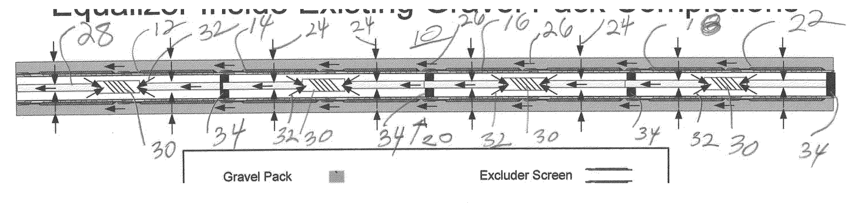
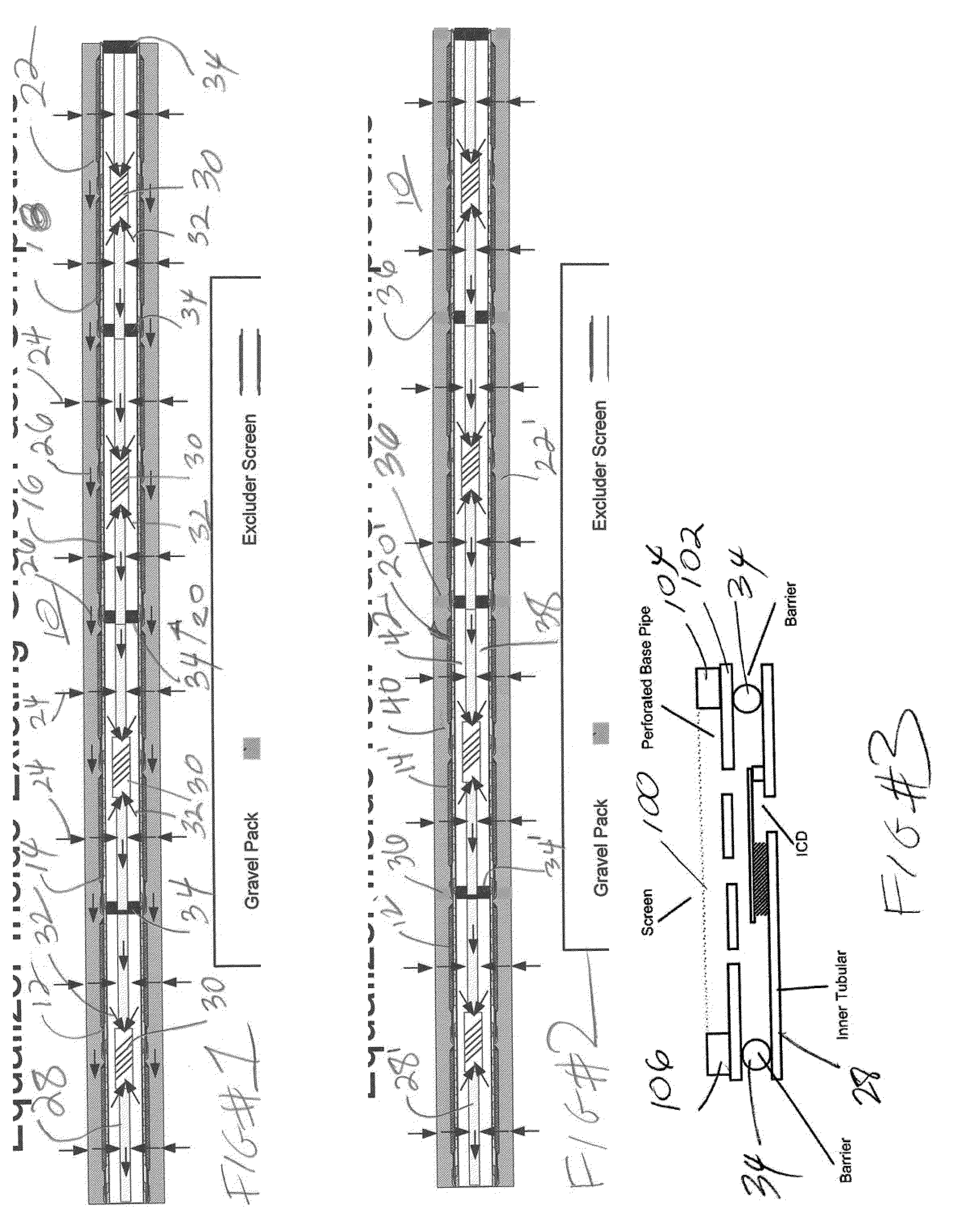
[0023]Referring to FIG. 1 a wellbore 10 which can be open hole or cased hole has a series of screen sections 12, 14, 16 and 18 joined together to make an assembly 20. Although no blank pipe sections are illustrated in assembly 20 it is within...


PUM


Abstract

An assembly of inflow control devices on a string along with isolation devices can be delivered into an existing or newly delivered screen assembly that requires inflow control for balanced flow from the formation. In newly delivered screen assemblies, any gravel packing that needs to be done can be accomplished without the presence of the inflow devices for faster circulation and improved gravel deposition. External annular barriers can also be delivered with an original screen assembly in a new well installation. The inflow devices and barriers can be of a variety of designs and the internal string can be removable if the barriers are retrievable to facilitate further drilling or completion below the screen assembly.

Description

FIELD OF THE INVENTION[0001]The field of the invention is control of flow through screen sections either newly run or retrofit in existing wells by using internal flow control devices on an inner string separated by barriers within the screen and optionally for new installations additional external annular barriers.BACKGROUND OF THE INVENTION[0002]Formations with long production intervals frequently provide an of imbalance of the incoming flow along the interval that leads to problems with water coning or other water production challenges, and also production of other undesirable fluids. Prior solutions have included balancing the flow along a long production interval with a plurality of inflow control devices, which may be designed, tuned, or manipulated to segment and distribute the inflow across the production interval to improve the inflow characteristics. Typically these devices have been integrated into an assembly including sand screen systems.[0003]Inflow control devices in ...

Claims


Application Information

Patent Timeline
Patent Type & Authority Applications(United States)
IPC IPC(8): E21B43/08E21B33/12E21B43/04E21B34/06E21B23/00E21B43/10
CPCE21B43/12
Inventor VICKERY, EUIN H.VOLL, BENNRATTERMAN, EUGENEBOWEN, EDDIEBROOME, JOHN T.
Owner BAKER HUGHES INC
Why Eureka
Try Eureka