Power tool

Active Publication Date: 2010-08-26
ROBERT BOSCH GMBH
View PDF28 Cites 13 Cited by
  • Summary
  • Abstract
  • Description
  • Claims
  • Application Information

AI Technical Summary

Benefits of technology

[0011]Particularly advantageously, the present invention may be used in a power tool that is designed as an electrical screwdriver, an electrical drill/driver, an electrical impact driver, a drill, an impact drill, or a rotary hammer, and that includes a multistage gearbox and/or a plurality of operating modes (e.g., drilling/impact drilling) since this results in a reduction of operating forces and minimal damage to the gearbox components. Preferably, the power tool may also include an axial drive device, in particular an impact drilling device.
[0012]It is also possible to provide a common operating element for the drive motor and the auxiliary device in order to simplify operation

Problems solved by technology

In the case of the known impact driver, it is no

Method used


Image

  • Power tool
  • Power tool
  • Power tool

Examples


Embodiment Construction

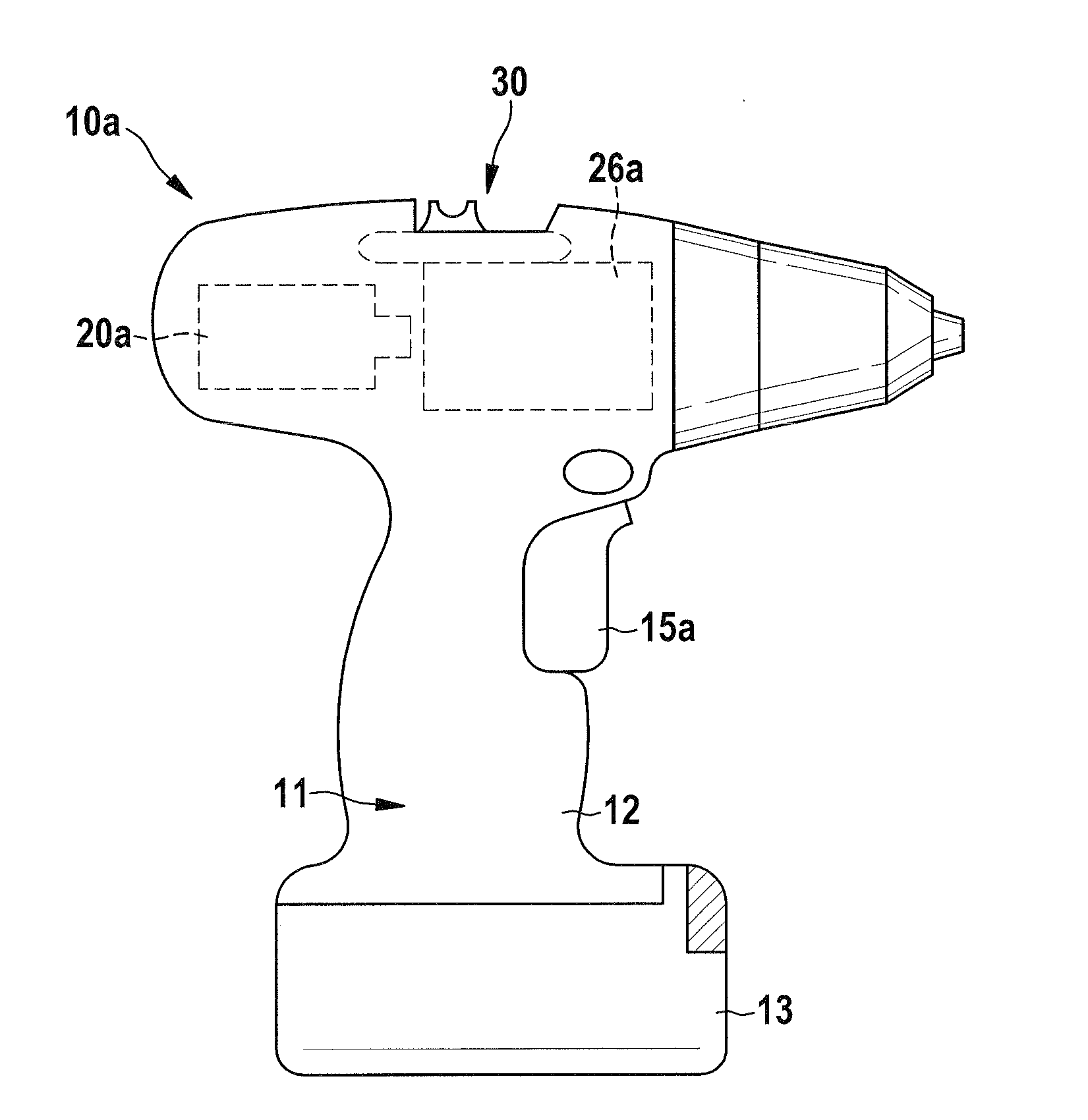
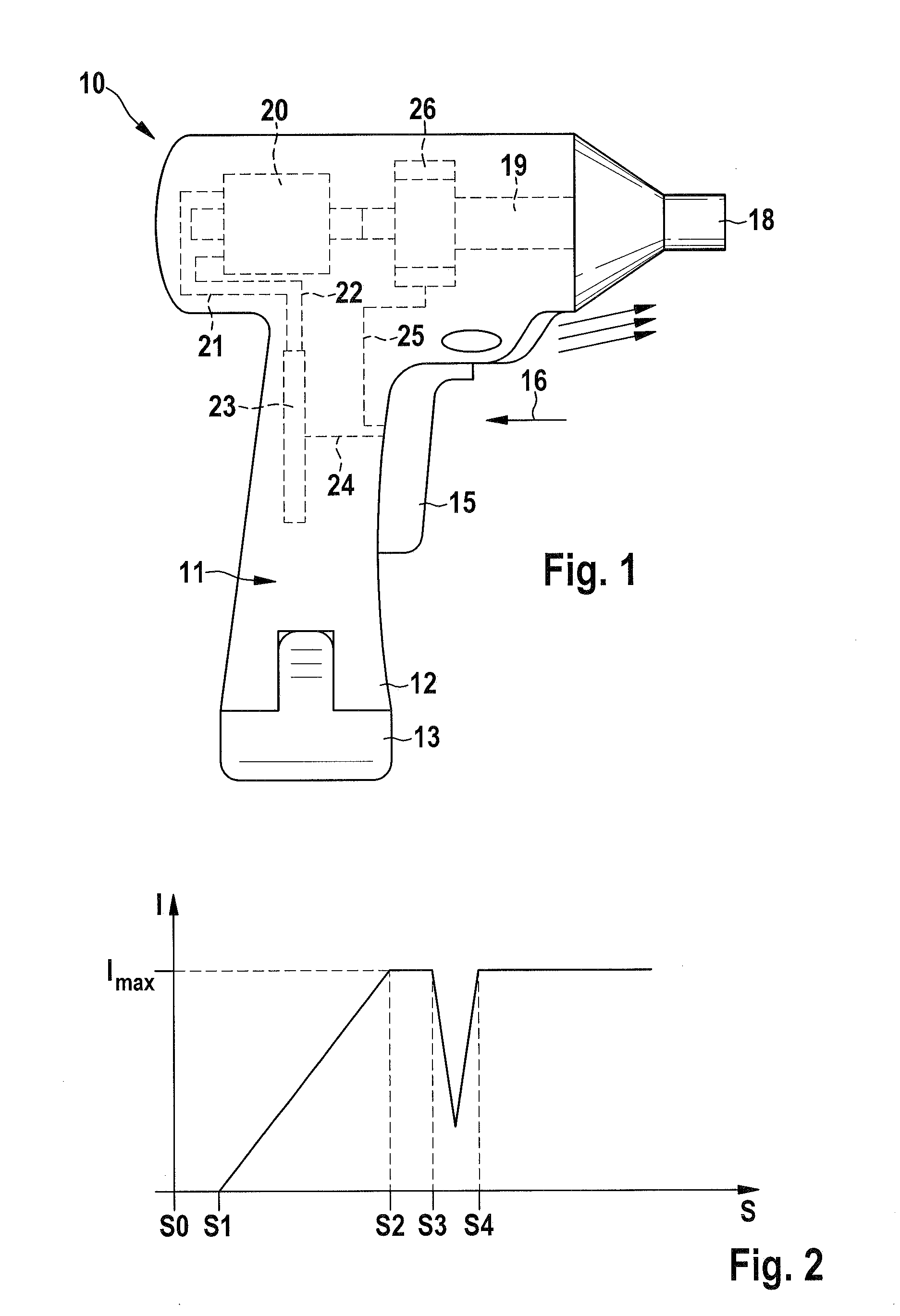
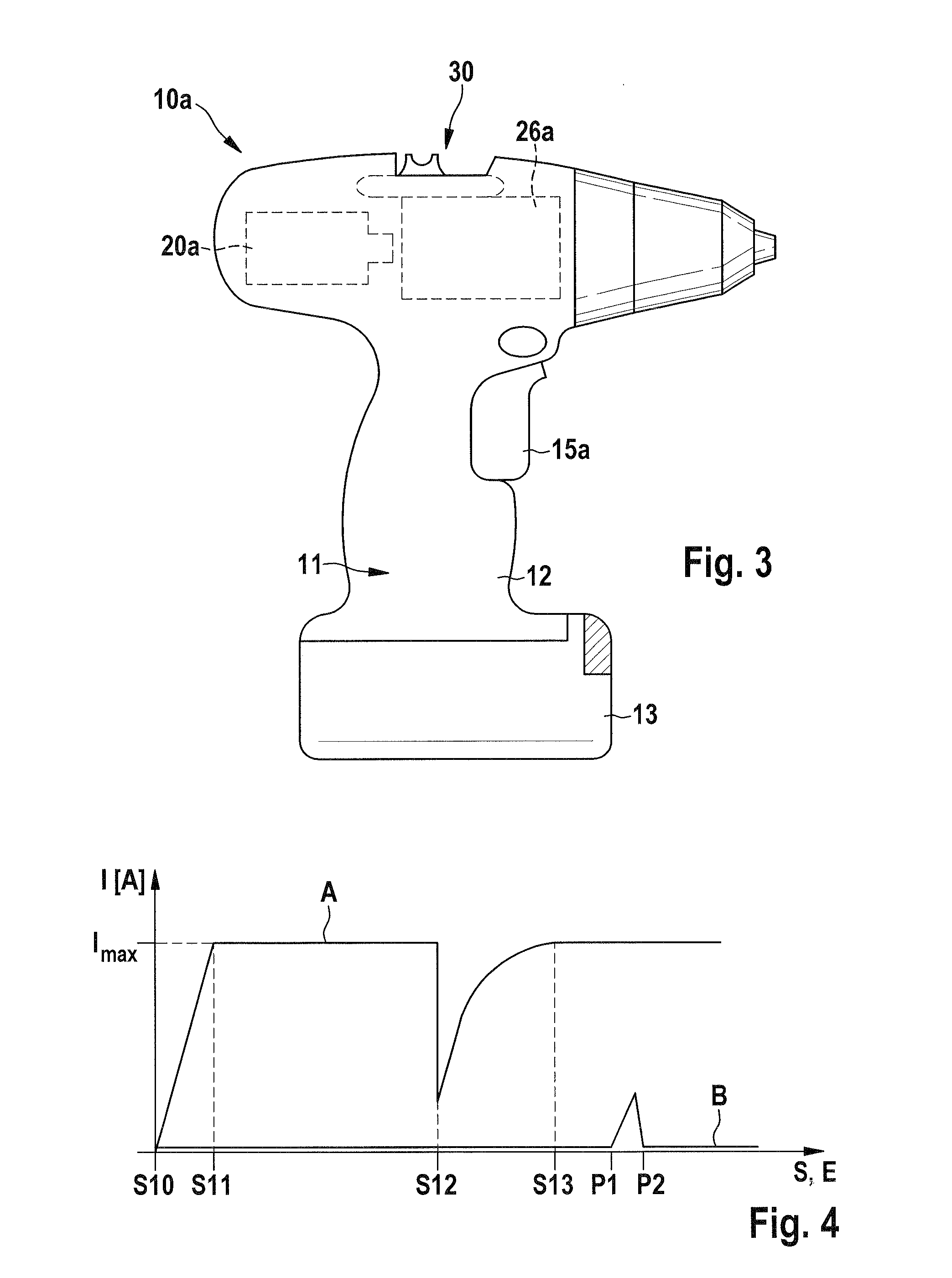
[0021]FIG. 1 shows a cordless drill 10 which includes a housing 11. A rechargeable battery pack 13, which is used as the energy source for the drive (motor) and electronics of cordless drill 10, is also shown on the lower end of handle 12. Furthermore, a switch lever 15, which may be moved by an operator in the direction of arrow 16, is supported on handle 12. A movement of switch lever 15 in the direction of arrow 16 will also be referred to below as displacement path S of switch lever 15.

[0022]Cordless drill 10 includes, in its interior, a drive motor 20 which is coupled to a drill chuck 18 or a spindle via a gearbox 19. Drive motor 20 is connected via lines 21, 22 to an output control switch 23 which is connected via a line 24 to switch lever 15, and is controlled by the same.

[0023]Switch lever 15 is also connected via a connection 25 to an automatic shifting device 26 designed as an auxiliary device. Shifting device 26 may switch, e.g., the gear reduction of gearbox 19 coupled t...


PUM

PropertyMeasurementUnit
Forceaaaaaaaaaa
Speedaaaaaaaaaa
Currentaaaaaaaaaa

Abstract

A power tool includes a drive motor and at least one auxiliary device, which is coupled to the drive motor, for activating at least two different operating states. The drive motor and the at least one auxiliary device are controllable using at least one operating device. The output of the drive motor is changed when the at least one auxiliary device is activated. As a result, the operating forces are reduced when switching between operating states, and the load on components is reduced.

Description

CROSS-REFERENCE TO A RELATED APPLICATION[0001]The invention described and claimed hereinbelow is also described in German Patent Application DE 10 2009 001 132.3 filed on Feb. 25, 2009. This German Patent Application, whose subject matter is incorporated here by reference, provides the basis for a claim of priority of invention under 35 U.S.C. 119(a)-(d).BACKGROUND OF THE INVENTION[0002]The present invention relates to power tools.[0003]Publication U.S. Pat. No. 6,800,045 B1 makes known a power tool, in the form of a drill, the gearbox of which is coupled to the drive motor and is connected to an auxiliary gear device. The auxiliary gear device automatically lowers the gear ratio during operation in accordance with the resistance to rotation presented. This means, for instance, that the rotational speed of the gearbox is reduced during drilling operation if the hardness of the material to be drilled increases. This is made possible via the known auxiliary gear device without the nee...

Claims


Application Information

Patent Timeline
IPC IPC(8): B25B21/00
CPCB23B45/008B25B21/008B25F5/001B25D2250/205B25D2250/221B25D16/006
Inventor ZIMMERMANN, THILOROEHM, HEIKOWELKE, JOERGSAUR, DIETMAR
Owner ROBERT BOSCH GMBH
Why Eureka
Try Eureka