
Mirror Image Target Detection and Recognition

a mirror image and target detection technology, applied in the direction of reradiation, measurement devices, instruments, etc., can solve the problems of substantial and costly processing capability of conventional automatic target recognition in the radar receiver

Active Publication Date: 2010-08-26
RAYTHEON CO
View PDF10 Cites 15 Cited by
  • Summary
  • Abstract
  • Description
  • Claims
  • Application Information

AI Technical Summary

Problems solved by technology

Such conventional automatic target recognition requires substantial and costly processing capability in the radar receiver.

Method used


Image

  • Mirror Image Target Detection and Recognition
  • Mirror Image Target Detection and Recognition
  • Mirror Image Target Detection and Recognition

Examples


Embodiment Construction

[0013]Description of Apparatus

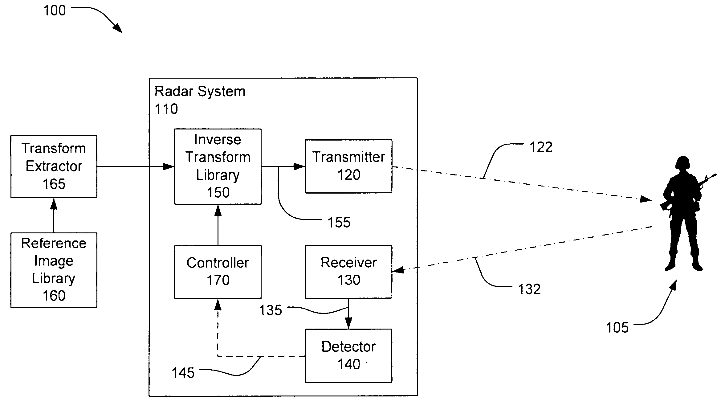
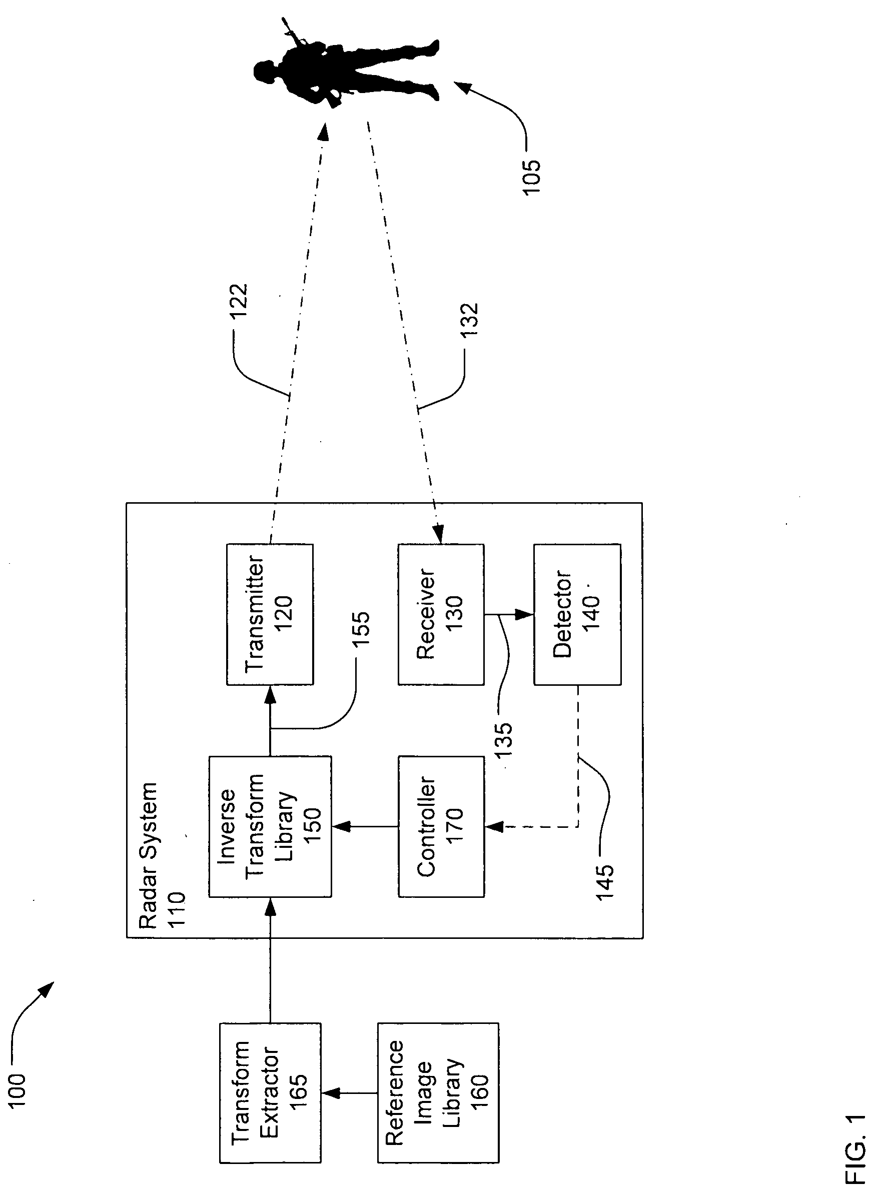
[0014]Referring now to FIG. 1, a system for identifying targets 100 using mirror image detection and recognition may include a radar system 110. The radar system 110 may include a transmitter 120 to transmit a radio-frequency signal 122 and a receiver 130 to receive a return signal 132 scattered, or reflected, from a scene which may contain a target 105. The transmitter 120 and receiver 130 may be coupled to separate antennas or a common antenna, which is not shown in FIG. 1.

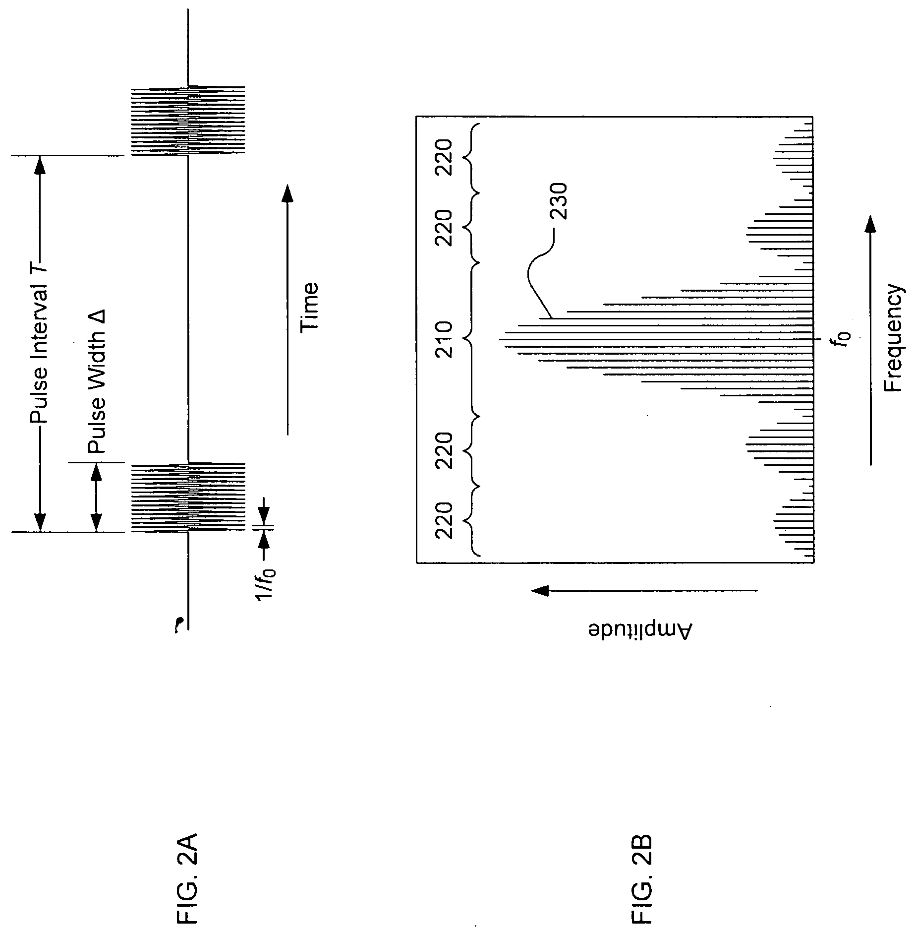
[0015]The transmitted radio frequency signal 122 may be modulated by an inverse transform data set 155 from an inverse transform library 150. The function of the inverse transform data set may be understood by briefly considering the radar signal waveforms shown in FIG. 2.

[0016]FIG. 2A shows a pulsed radio-frequency waveform which may be representative of the waveform transmitted by a conventional radar system. The pulsed radio-frequency waveform may be comprised of periodic pulses ...


PUM


Abstract

There is disclosed a system and method for detecting targets. A transmitter may transmit a first inverse transform signal, the first inverse transform signal derived from a reference image of a first reference target at a first aspect angle. A receiver may receive a return signal reflected from a scene. A detector may determine, based on the return signal, if an object similar to the first target at the first aspect angle is detected within the scene.

Description

NOTICE OF COPYRIGHTS AND TRADE DRESS[0001]A portion of the disclosure of this patent document contains material which is subject to copyright protection. This patent document may show and / or describe matter which is or may become trade dress of the owner. The copyright and trade dress owner has no objection to the facsimile reproduction by anyone of the patent disclosure as it appears in the Patent and Trademark Office patent files or records, but otherwise reserves all copyright and trade dress rights whatsoever.BACKGROUND[0002]1. Field[0003]This disclosure relates to detecting and identifying targets using a radar system.[0004]2. Description of the Related Art[0005]Radar systems typically transmit an RF signal and receive a portion of the RF signal returned or reflected from targets and other objects. While radars may transmit a wide variety of signals, a common form of radar transmits a narrow beam of RF energy, typically within the microwave or millimeter wave portions of the el...

Claims


Application Information

Patent Timeline
Patent Type & Authority Applications(United States)
IPC IPC(8): G01S13/00
CPCG01S7/024G01S13/887G01S7/412G01S7/282
Inventor BIRDSONG, JR., FRANK A.KINSEY, JR., LLOYD E.
Owner RAYTHEON CO
Learn More