

Capacitor and method of manufacturing the same
a technology of capacitors and capacitors, applied in the field of capacitors, can solve the problems of limiting the improvement of the capacitance of the capacitor, and achieve the effect of increasing the capacitance and reducing the dielectric loss of the capacitor
- Summary
- Abstract
- Description
- Claims
- Application Information
AI Technical Summary
Benefits of technology
Problems solved by technology
Method used
Image

Examples
first embodiment
Structure of a Capacitor in Accordance with the First Embodiment
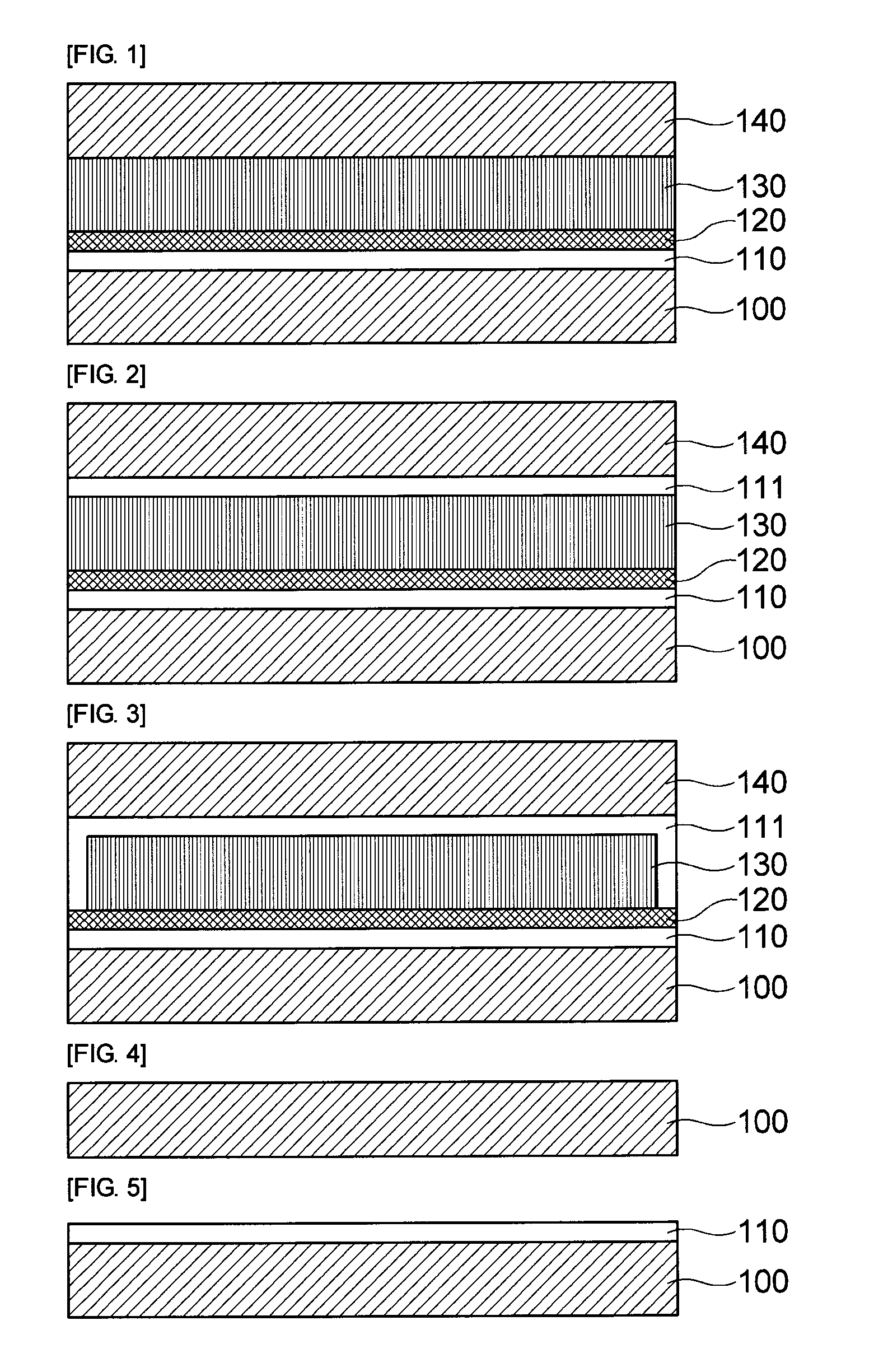
[0036]A capacitor in accordance with the first embodiment of the present invention will be described in detail with reference to FIG. 1.
[0037]FIG. 1 is a cross-sectional view showing a structure of a capacitor in accordance with the first embodiment of the present invention
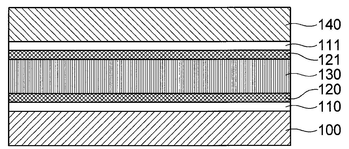
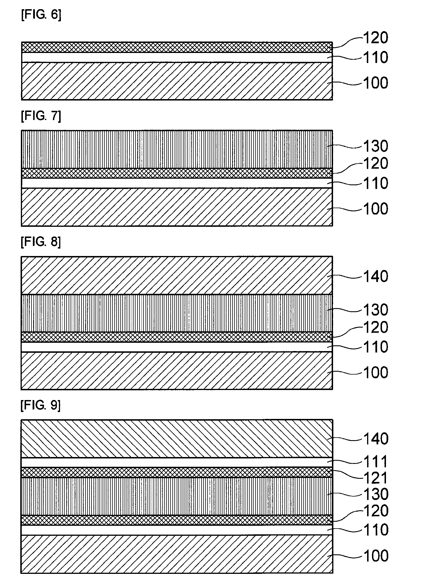
[0038]As shown in FIG. 1, the capacitor in accordance with the first embodiment of the present invention includes a bottom electrode 100, a first dielectric layer 110 formed on the bottom electrode 100, a conductive polymer layer 120 formed on the first dielectric layer 110, a second dielectric layer 130 formed on the conductive polymer layer 120, and a top electrode 140 formed on the second dielectric layer 130.
[0039]The bottom electrode 100 and the top electrode 140 may be made of metal such as Cu. Further, the bottom and top electrodes 100 and 140 may be made of Ni, Al, Pt, Pd, Ta, Au, Ag, or the like as well as Cu.
[0040]And, the first dielectric l...
first modified example
[0053]A first modified example of the first embodiment of the present invention will be described with reference to FIG. 2. Description of the same configuration of the first modified example of the first embodiment as that of the first embodiment will be omitted and only different configuration of the first modified example will be described in detail.
[0054]FIG. 2 is a cross-sectional view showing a structure of a capacitor in accordance with the first modified example of the first embodiment of the present invention.
[0055]As shown in FIG. 2, the capacitor in accordance with the first modified example of the first embodiment of the present invention includes most of the same components as those of the capacitor of the first embodiment as described above, only it is different from the capacitor of the first embodiment in that a third dielectric layer 111 having the same dielectric constant as that of the first dielectric layer 110 is further formed between the second dielectric laye...
second modified example
[0057]A second modified example of the first embodiment of the present invention will be described with reference to FIG. 3. Description of the same configuration of the second modified example as that of the first embodiment will be omitted and only different configuration of the second modified example will be described in detail.
[0058]FIG. 3 is a cross-sectional view showing a structure of a capacitor in accordance with the second modified example of the first embodiment of the present invention.
[0059]As shown in FIG. 3, the capacitor in accordance with the second modified example of the first embodiment of the present invention includes most of the same components as those of the capacitor of the first embodiment as described above, only it is different from the capacitor of the first embodiment in that a third dielectric layer 111 surrounding a top surface and both lateral surfaces of the second dielectric layer 130 formed on the conductive polymer layer 120 is further provided...
PUM
 Abstract
Description
Claims
Application Information