
Light emitting device with a solar bulb

a technology of light emitting devices and solar panels, which is applied in the direction of semiconductor devices for light sources, lighting and heating apparatuses with built-in power, etc., can solve the problems of chemical energy not being supplied by charging batteries, pollution, and inconvenient operation of electronic devices,

Inactive Publication Date: 2010-08-26
MINIWIZ CO LTD
View PDF11 Cites 19 Cited by
  • Summary
  • Abstract
  • Description
  • Claims
  • Application Information

AI Technical Summary

Benefits of technology

[0006]An exemplary embodiment of a light emitting device is disclosed. The light emitting device includes a bottle, and a solar bulb for capping with the bottle. The solar bulb includes a housing, a solar panel disposed on the housing for converting solar energy into electric energy, a rechargeable battery module installed inside the housing for storing the electric energy generated by the solar panel, a light source installed inside the housing for emitting light to the bottle, and a control circuit installed inside the housing and coupled to the solar panel and the rechargeable battery module for transmitting the electric energy from the rechargea...

Problems solved by technology

The non-rechargeable battery only can be used once, and chemical energy can not be supplied by charging the battery.
However, when the non-rechargeable battery and the rechargeable battery run out of electricity, the non-rechargeable battery and the rechargeable battery can not provide electricity anymore at the moment, causing inconvenient to operate electronic apparatuses.
In addition, the chemical battery has disadvantages of difficulty of recycling, pollution, and low charging speed.
Thus, it is time and energy consuming to use the hand-powered device to charge electronic products.
Besides, charging efficiency of a hand-powered device is not as good as that of a solar charger.

Method used


Image

  • Light emitting device with a solar bulb
  • Light emitting device with a solar bulb
  • Light emitting device with a solar bulb

Examples


Embodiment Construction

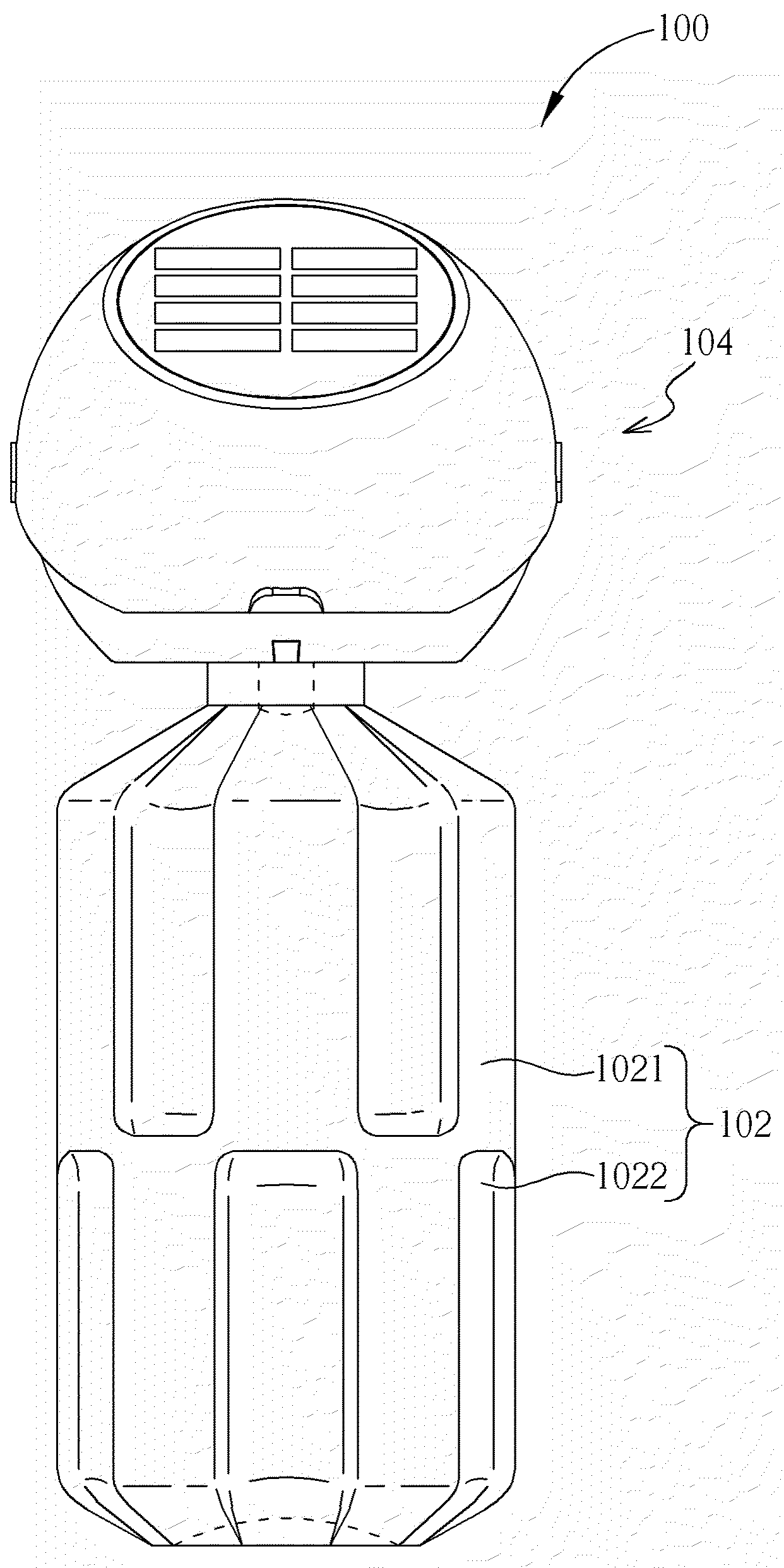
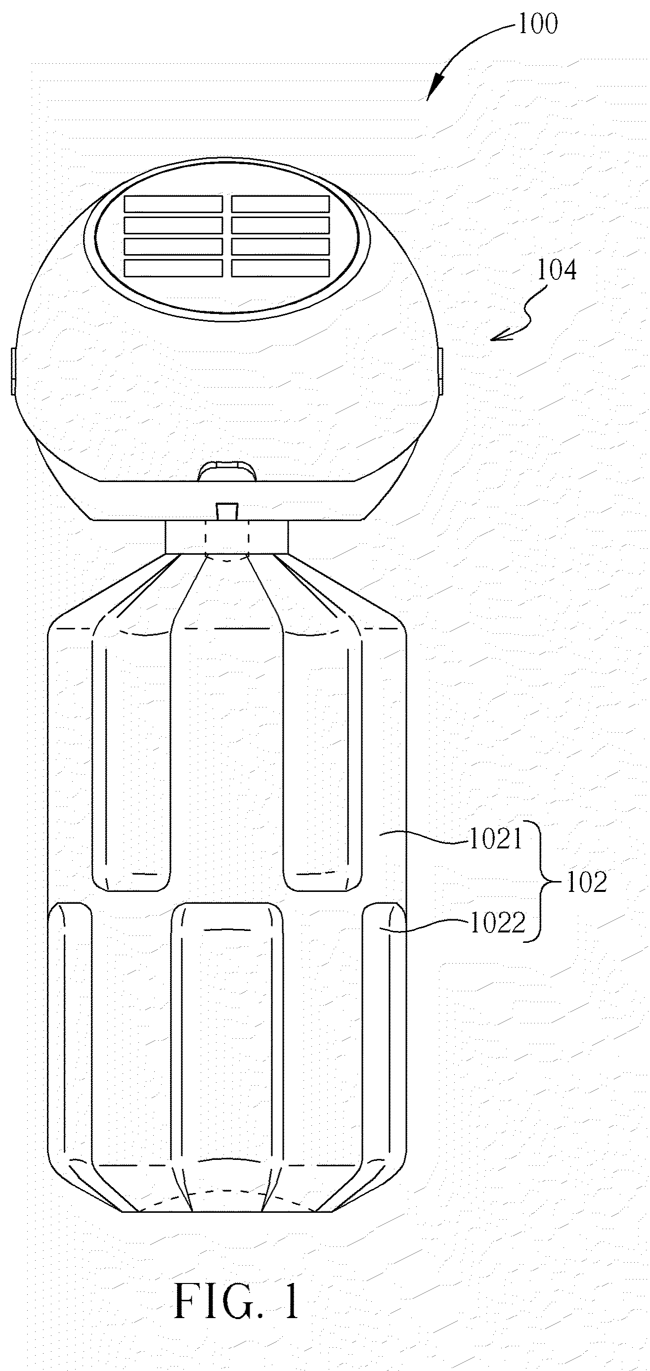
[0013]Please refer to FIG. 1. FIG. 1 is a perspective drawing of a light emitting device 100 according to a preferred embodiment of the present invention. The light emitting device 100 includes a bottle 102, and a solar bulb 104 capped with the bottle 102. The solar bulb 104 can be screwed on the bottle 102 as a bottle cap. Fluid, such as water, can be contained inside the bottle 102. The bottle 102 includes alternate a plurality of protruding parts 1021 and a plurality of sunken parts 1022. The disposition and the amount of the plurality of protruding parts 1021 and the plurality of sunken parts 1022 are not limited to this embodiment and can be designed upon actual demand. The bottle 102 also can include a smooth surface instead.

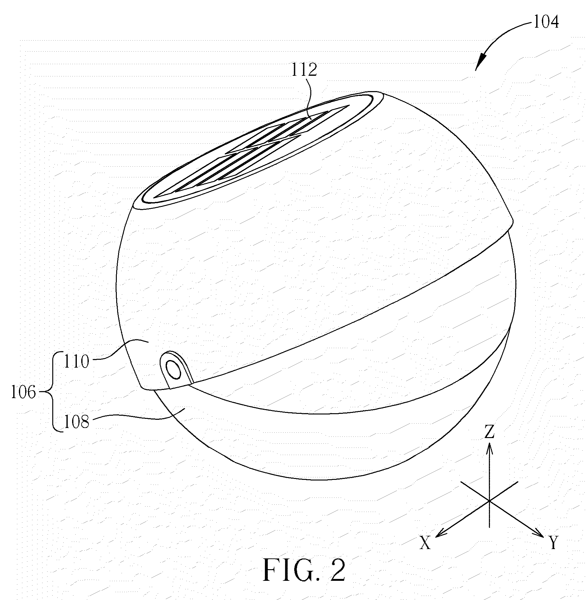
[0014]Please refer to FIG. 2 to FIG. 5. FIG. 2 to FIG. 4 are perspective drawings at different views of the solar bulb 104 according to the preferred embodiment of the present invention. FIG. 5 is a diagram illustrating inner components of the solar bulb 1...


PUM


Abstract

A light emitting device is disclosed. The light emitting device includes a bottle, and a solar bulb for capping with the bottle. The solar bulb includes a housing, a solar panel disposed on the housing for converting solar energy into electric energy, a rechargeable battery module installed inside the housing for storing the electric energy generated by the solar panel, a light source installed inside the housing for emitting light to the bottle, and a control circuit installed inside the housing and coupled to the solar panel and the rechargeable battery module for transmitting the electric energy from the rechargeable battery module to the light source.

Description

BACKGROUND OF THE INVENTION[0001]1. Field of the Invention[0002]The present invention relates to a light emitting device with a solar bulb, and more particularly, to a light emitting device with a solar bulb capable of converting solar energy into electric energy for lightening.[0003]2. Description of the Prior Art[0004]In general, a chemical battery can transfer chemical energy into electric energy. The chemical battery includes advantages of portability, high energy density, no noise, and so on, so the chemical battery is widely used in a notebook computer, and portable electronic apparatus, such as mobile phones and digital cameras. There are two kinds of the chemical battery, a non-rechargeable battery and a rechargeable battery. The non-rechargeable battery only can be used once, and chemical energy can not be supplied by charging the battery. The non-rechargeable batteries are a dry battery, a mercury battery, an alkaline battery, and so on. The rechargeable battery can be use...

Claims


Application Information

Patent Timeline
IPC IPC(8): F21L4/00
CPCF21S9/037B65D51/248F21Y2101/02F21V33/0036F21Y2101/00F21Y2115/10F21Y2115/30Y02W30/82
Inventor LIU, TZU-WEIHUANG, CHIAN-CHIHUANG, MIN-FENG
Owner MINIWIZ CO LTD
Learn More