Rotor assembly

a high-speed compressor and rotor technology, which is applied in the direction of bearings, shafts, motors, etc., can solve the problems of prolonging the life of bearings, and achieve the effects of ensuring the alignment of the shaft within the housing, prolonging the life of bearings, and ensuring the radial load of the two bearings

Inactive Publication Date: 2010-08-26
DYSON TECH LTD
View PDF35 Cites 44 Cited by
  • Summary
  • Abstract
  • Description
  • Claims
  • Application Information

AI Technical Summary

Benefits of technology

[0005]The rotor assembly is therefore supported by two preloaded bearings. The bearings are ideally spaced by a predetermined amount and the spring has a predetermined spring constant. Consequently, the two bearings are preloaded with the same, well-defined force. By preloading the bearings with a force that prevents skidding without being excessive, the lifetime of the bearings is increased.
[0015]The bearing cartridge provides a single fastening over which the rotor assembly may be secured to a housing, frame or the like. The provision of two spaced bearings affords relatively good stability, while the sleeve acts to align the bearings and serves as a heat sink. Since the sleeve and shaft are thermally matched, thermal expansion of the shaft and sleeve does not adversely affect the loading of the bearings during subsequent use.

Problems solved by technology

The sleeve also acts as a heat sink for the bearings, thus prolonging the life of the bearings.

Method used


Image

  • Rotor assembly
  • Rotor assembly

Examples


Embodiment Construction

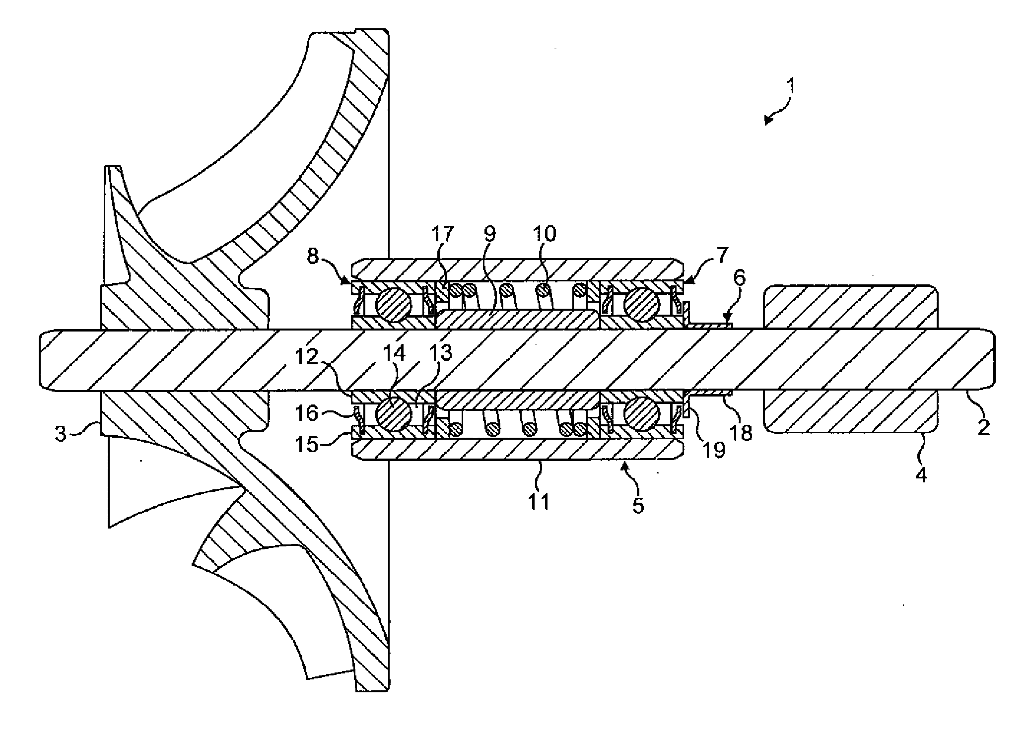
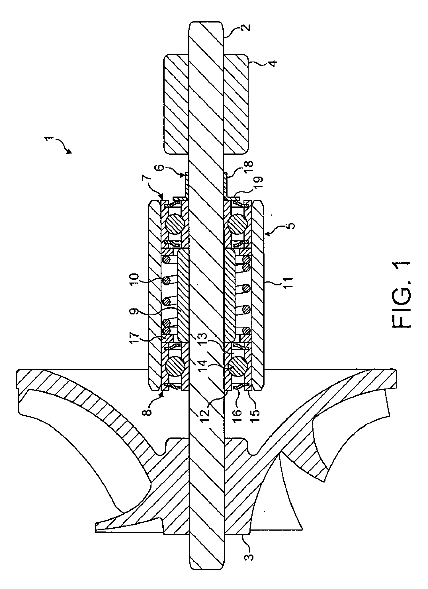
[0019]The rotor assembly 1 of FIG. 1 comprises a shaft 2 to which are mounted an impeller 3, a rotor core 4, a bearing cartridge 5, and a dirt cap 6.

[0020]The impeller 3 is mounted to a first end of the shaft 2. The impeller 3 illustrated in FIG. 1 is a centrifugal impeller. However, other types of impeller may equally be employed according to the intended application of the rotor assembly 1.

[0021]The rotor core 4 is mounted to a second end of the shaft 2. The rotor core 4 is formed of a hard or soft magnetic material. The shaft 2 is formed of a soft magnetic material which then reduces the reluctance of the magnetic circuit. Nevertheless, a non-magnetic material might alternatively be used for the shaft 2.

[0022]The bearing cartridge 5 is located between the impeller 3 and the rotor core 4. The bearing cartridge 5 comprises a pair of bearings 7,8, a spacer 9, a spring 10, and a sleeve 11.

[0023]The bearings 7,8 are identical, with each comprising an inner race 12, a cage 13 supportin...


PUM


Abstract

A rotor assembly that includes a shaft to which are mounted an impeller, a rotor core and a bearing cartridge. The bearing cartridge is mounted between the impeller and the rotor core and comprises a pair of bearings, a spring that applies a preload to each of the bearings, and a sleeve that surrounds the bearings.

Description

REFERENCE TO RELATED APPLICATIONS[0001]This application claims the priority of United Kingdom Application No. 0903053.7, filed Feb. 24, 2009, the entire contents of which are incorporated herein by reference.FIELD OF THE INVENTION[0002]The present invention relates to a rotor assembly for a high-speed compressor.BACKGROUND OF THE INVENTION[0003]The rotor assembly of many high-speed compressors includes a shaft mounted to a housing by a pair of bearings, each bearing located at opposite ends of the shaft. The provision of bearings at opposite ends of the shaft affords good stability. However, the pathway between the two bearings through the housing is relatively long and typically traverses several distinct components of the compressor. As a consequence of dimensional and geometric tolerances, it is generally difficult to ensure that the rotor assembly is accurately aligned within the housing. Additionally, for high-speed compressors, the bearings are ideally preloaded to prevent ski...

Claims


Application Information

Patent Timeline
Patent Type & Authority Applications(United States)
IPC IPC(8): F04D29/046
CPCF04D29/0563F04D29/059F16C25/083F16C35/077F16C35/12F16C19/55F16C19/06F16C19/54F16C2360/44F16C2380/26F01D25/162F04D29/0462F16C35/04F16C39/02F04D29/056F16C25/08
Inventor MOCKRIDGE, RICHARD IAINGREETHAM, STEPHENCHILDE, MATTHEW JOHN
Owner DYSON TECH LTD
Why Eureka
Try Eureka