Dental implant

a technology of dental implants and implants, applied in dental implants, dental surgery, medical science, etc., can solve the problems of total destruction of bone threads

Inactive Publication Date: 2010-08-26
KRUSH VICTOR +1
View PDF4 Cites 7 Cited by
  • Summary
  • Abstract
  • Description
  • Claims
  • Application Information

AI Technical Summary

Benefits of technology

[0005]The object of the present invention is to prevent the disadvantages of the before mentioned prior art dental devices and to provide a firm implant installation.

Problems solved by technology

This leads to a total destruction of the thread made in the bone.

Method used


Image

  • Dental implant
  • Dental implant
  • Dental implant

Examples


Embodiment Construction

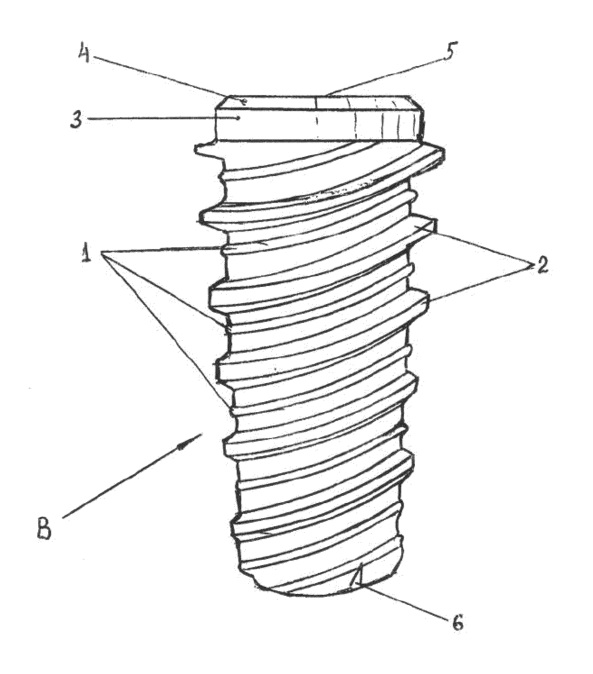
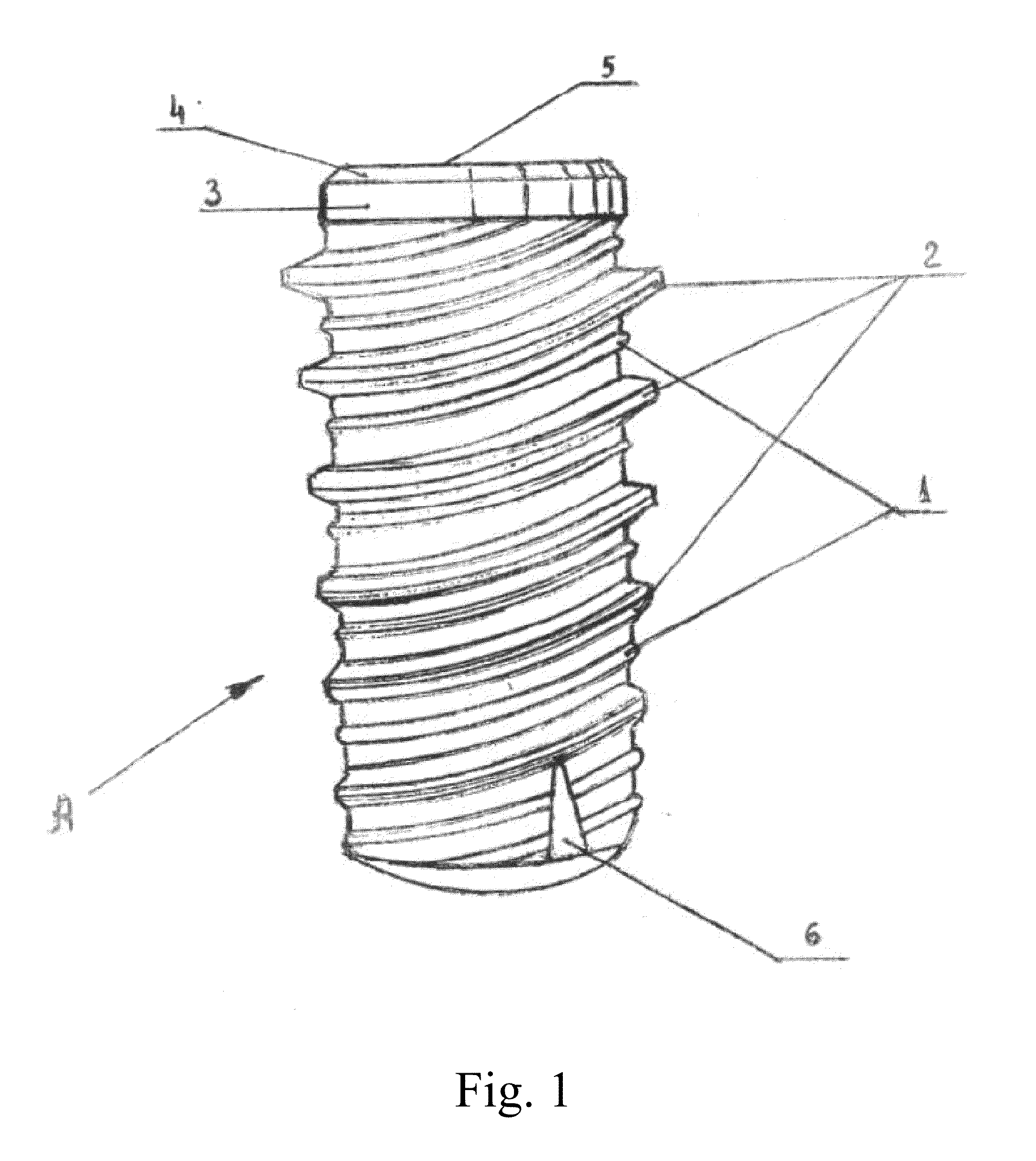
[0015]Referring to FIG. 1, there is an illustration of a commonly used prior art of dental implant A includes: 1-microcarved lead threads, 2-increasing value of teeth of the second lead threads, 3-untreaded cylindrical portion, 4-proximal untreaded portion, 5-flat surface atop dental implant, 6-antigingival growth barrier. (numbers of the FIG. 1 are corresponding numbers of the FIGS. 3 and 4)

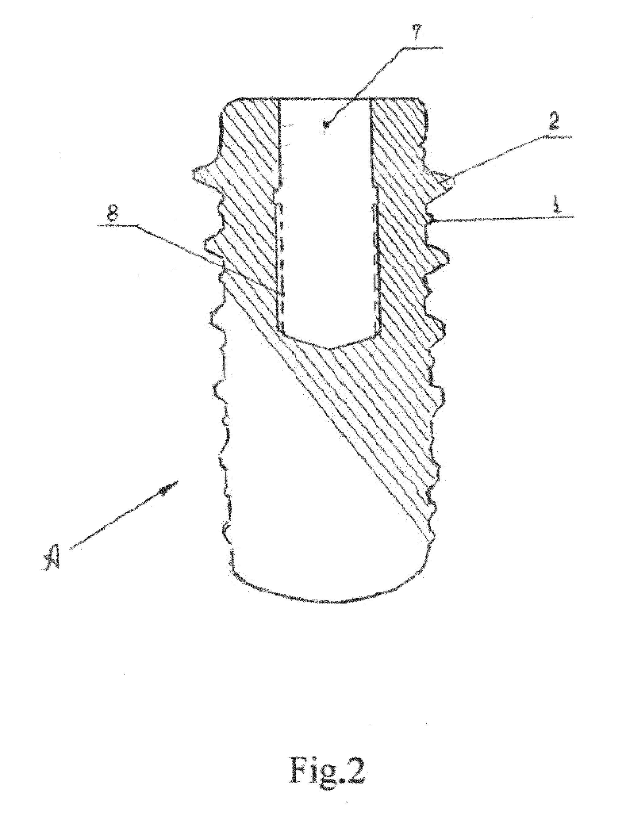
[0016]Referring to FIG. 2 shown cross-section of the said implant A, where 7-opening for block of the implant, 8-internal lead threads.

[0017]For instance, if the said implant has a micro carving diameter of 3,7 mm and a length 13 mm, then the maximal diameter of the second lead threads must be ≈ 4,5 mm. Thereat, first drill must have a diameter of 3,2 mm and a length (depth) of 13 mm, while the second drill must have a diameter of 3,7 mm and a length (depth) of 3 mm. Therefore, this construction permits to increase the surface of area of the implant and the loads put on the implant. This is espe...


PUM


Abstract

The invention provides a dental implant, characterized by a cylindrically threaded shaft section with at least a double lead thread. One lead thread is micro carved, while the other lead thread is carved with teeth of any shape, for instance V-shaped, buttress-shaped or square-shaped. The dimension of teeth increases gradually from zero in the lower part of the said implant (with constant or cone diameter) to approximately 0.1-0.2 of the diameter of the micro carving from the upper part of the said body implant. The maximal diameter of the said implant equals approximately 1.2-1.4 of that of the lower part. Thereto the internal body is supplied by a lead thread in order to block the said implant and may further be used for attachment of the key to turn in the said implant.

Description

CROSS-REFERENCE TO RELATED APPLICATIONS[0001]This application claims priority benefit from Israel Patent Application No. 197178, filed Feb. 23, 2009, the contents of which are herein incorporated by reference in their entirety.FIELD OF THE INVENTION[0002]The present invention relates to dental devices and more specifically to dental implant.BACKGROUND OF THE INVENTION[0003]First, in order to install a dental implant, one needs to drill a hole in the bone in accordance to the design of the used implant. Several types of drills may be used, including those with a permanent, cone or increasing steps diameter.[0004]Further, when the implant is turned in, carving is formed within the bone. Then, while the bone is healing it often sinks down, so that the implant projects over the bone edge. This leads to a total destruction of the thread made in the bone.SUMMARY OF THE INVENTION[0005]The object of the present invention is to prevent the disadvantages of the before mentioned prior art dent...

Claims


Application Information

Patent Timeline
Patent Type & Authority Applications(United States)
IPC IPC(8): A61C8/00
CPCA61C8/0022A61C8/0025A61C8/0024
Inventor KRUSH, VICTORLOZINSKI, YULI
Owner KRUSH VICTOR
Why Eureka
Try Eureka