
Patient Specific Surgical Guide Locator and Mount

a patient-specific, surgical technology, applied in the field of surgical guides, can solve the problems of gate problems, patient discomfort, and degradation of prostheses, and none of the forgoing methods or devices have adequately provided surgeons with a way to generate patient-specific prostheses, surgical instruments, guides, fixtures, etc., to reduce the number or complexity of fixtures used

Active Publication Date: 2010-08-26
MICROPORT ORTHOPEDICS HLDG INC
View PDF100 Cites 283 Cited by
  • Summary
  • Abstract
  • Description
  • Claims
  • Application Information

AI Technical Summary

Benefits of technology

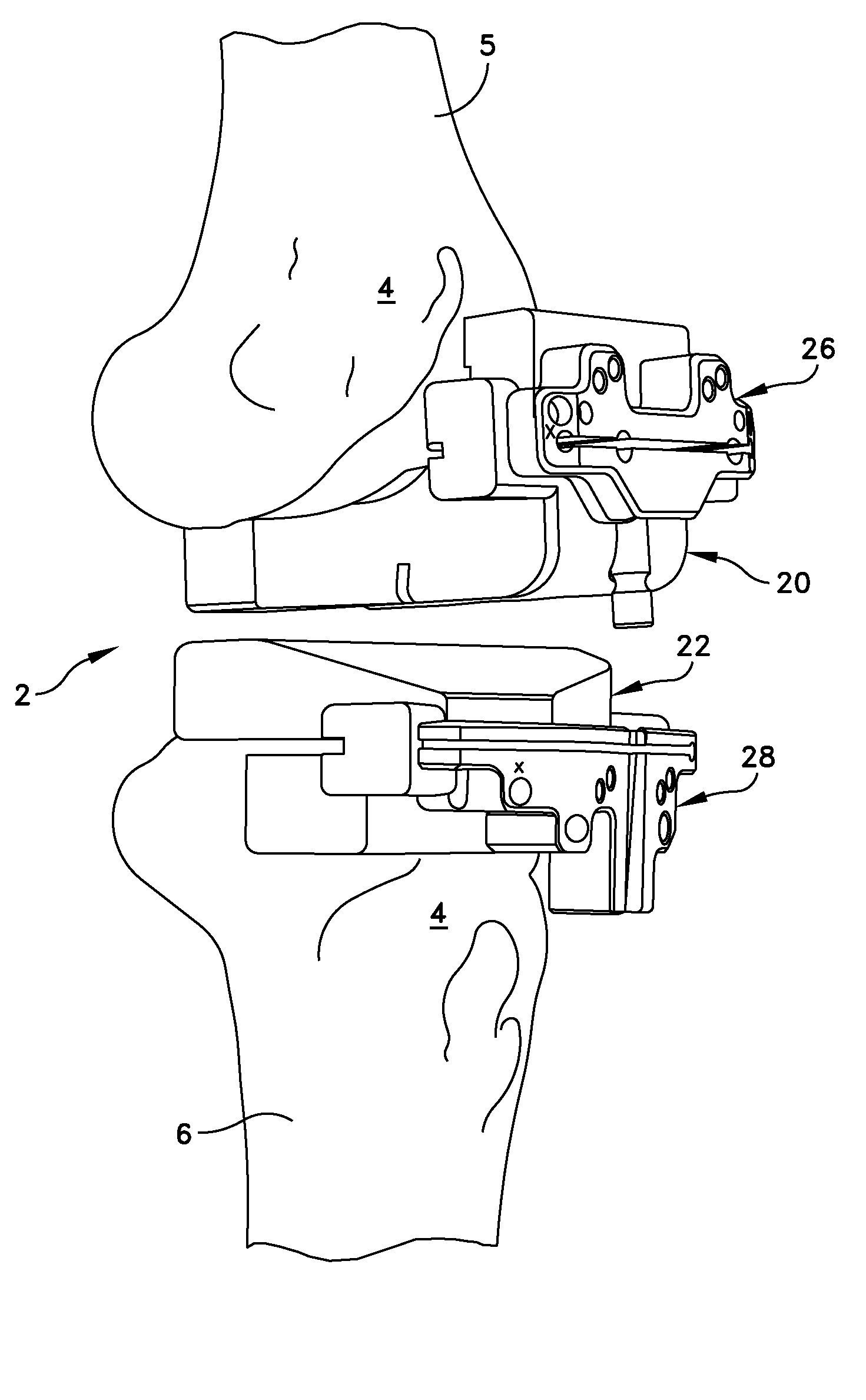
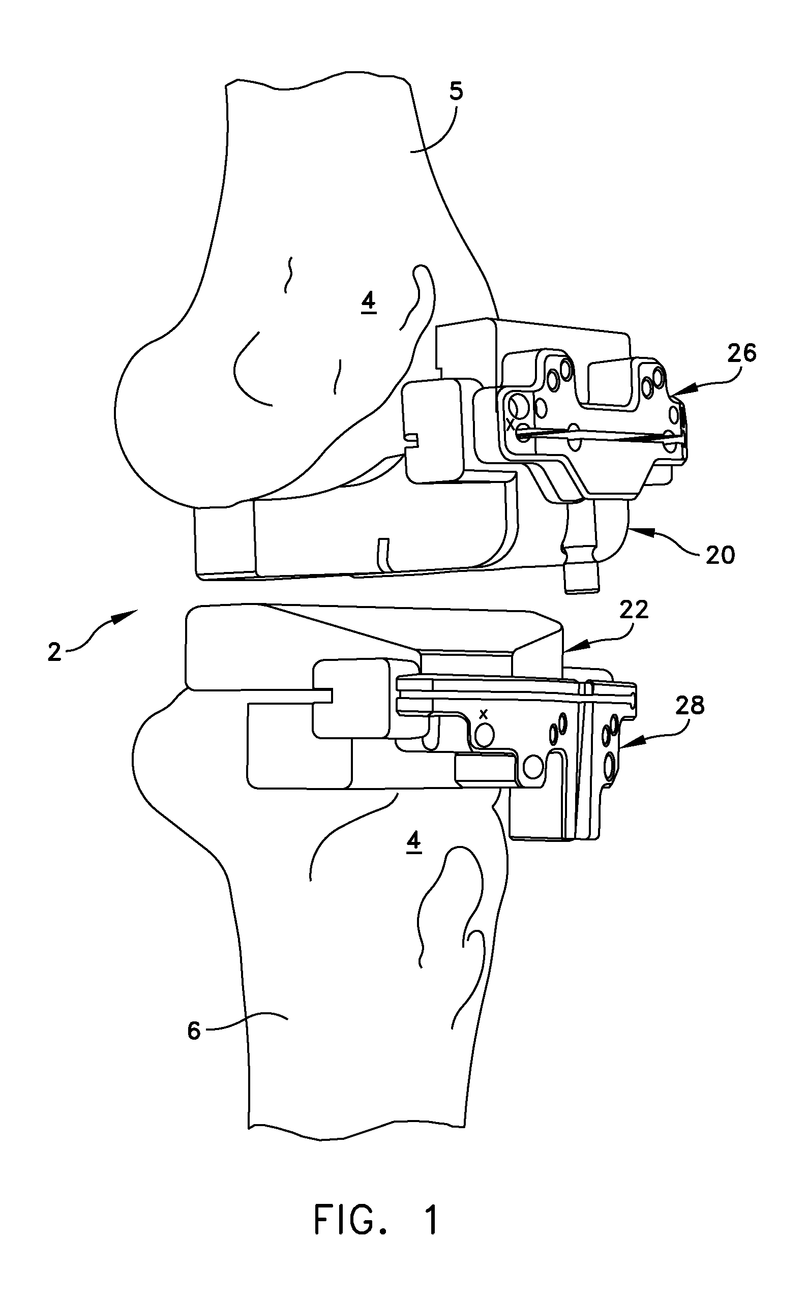
[0012]In another embodiment of the invention, a resection guide locator is provided that includes a bone engagement portion with two surfaces that are complementary to respective separate surface topographies of a bone to be resected during surgery. A housing portion is attached to the bone engaging portion, and includes a socket defined by a resilient annular wall that is sized and arranged so to accept a resection guide by press-fit to thereby position and hold the resection guide within the socket. In this way, the resection guide is maintained in a predetermined, preferred position while the two surfaces are releasably locked in position on the bone.

Problems solved by technology

Should the prosthesis not be properly attached to the femur, tibia, ankle or foot, any misalignment could result in discomfort to the patient, gate problems, or degradation of the prosthesis.
None of the forgoing methods or devices have adequately provided surgeons with a way to generate patient specific prostheses, surgical instruments, guides, and fixtures, nor have they aided in reducing the number or complexity of the fixtures used to locate resection guides in relation to the patient's body during orthopedic procedures, such as, total knee, hip, or ankle replacement surgery.

Method used


Image

  • Patient Specific Surgical Guide Locator and Mount
  • Patient Specific Surgical Guide Locator and Mount
  • Patient Specific Surgical Guide Locator and Mount

Examples


Embodiment Construction

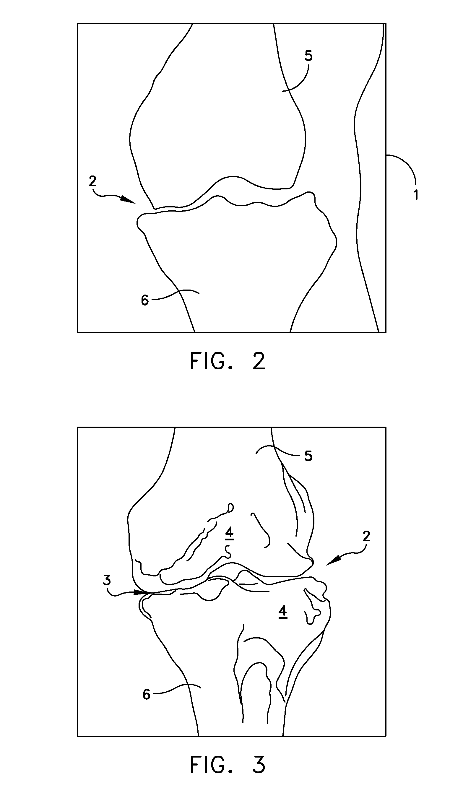
[0050]This description of preferred embodiments is intended to be read in connection with the accompanying drawings, which are to be considered part of the entire written description of this invention. The drawing figures are not necessarily to scale and certain features of the invention may be shown exaggerated in scale or in somewhat schematic form in the interest of clarity and conciseness. In the description, relative terms such as “horizontal,”“vertical,”“up,”“down,”“top” and “bottom” as well as derivatives thereof (e.g., “horizontally,”“downwardly,”“upwardly,” etc.) should be construed to refer to the orientation as then described or as shown in the drawing figure under discussion. These relative terms are for convenience of description and normally are not intended to require a particular orientation. Terms including “inwardly” versus “outwardly,”“longitudinal” versus “lateral” and the like are to be interpreted relative to one another or relative to an axis of elongation, or...


PUM

PropertyMeasurementUnit
surface topographyaaaaaaaaaa
shapeaaaaaaaaaa
sizeaaaaaaaaaa

Abstract

A resection guide locator includes a bone engagement portion with surfaces that are complementary to the surface topographies of a bone to be resected during surgery. A housing includes a socket defined by a resilient annular wall that is sized and arranged so to accept a resection guide by press-fit to thereby position and hold the resection guide within the socket. The resection guide is maintained in a predetermined, preferred position while the surfaces are releasably locked in position on the bone. A method is disclosed for forming and using the resection guide locator.

Description

[0001]This application is related to, and claims the benefit of U.S. provisional patent application Ser. No. 61 / 154,845, filed Feb. 24, 2009, and entitled Patient Specific Surgical Guide Mount.FIELD OF THE INVENTION[0002]The present invention generally relates to surgical guides, and the fixtures used to locate such guides in relation to a patient's body during orthopedic procedures, such as, total knee, hip, or ankle replacement surgery, and methods for designing and using such instrument locators.BACKGROUND OF THE INVENTION[0003]Total joint (knee, hip, and ankle) replacement prostheses are known in the art. In many instances, a specially designed jig or fixture enables the surgeon to make accurate and precise bone resections of the femoral surface, the tibial surface, or both in order to accept such prostheses. The ultimate goal with any total joint prosthesis is to approximate the function of the natural, healthy structures that the prosthesis is replacing. Should the prosthesis ...

Claims


Application Information

Patent Timeline
Patent Type & Authority Applications(United States)
IPC IPC(8): A61B17/56B23P11/02
CPCA61B17/155A61B17/157A61B2017/0023Y10T29/49A61B17/151Y10T29/49863A61B2017/568A61B2034/104A61B34/10A61B2034/108B33Y70/00B33Y80/00A61B17/154G06F30/00B29C64/386B33Y50/02A61B2017/00526G05B15/02
Inventor CARROLL, MICHAELOBERT, RICHARDSTEMNISKI, PAUL
Owner MICROPORT ORTHOPEDICS HLDG INC
Learn More