

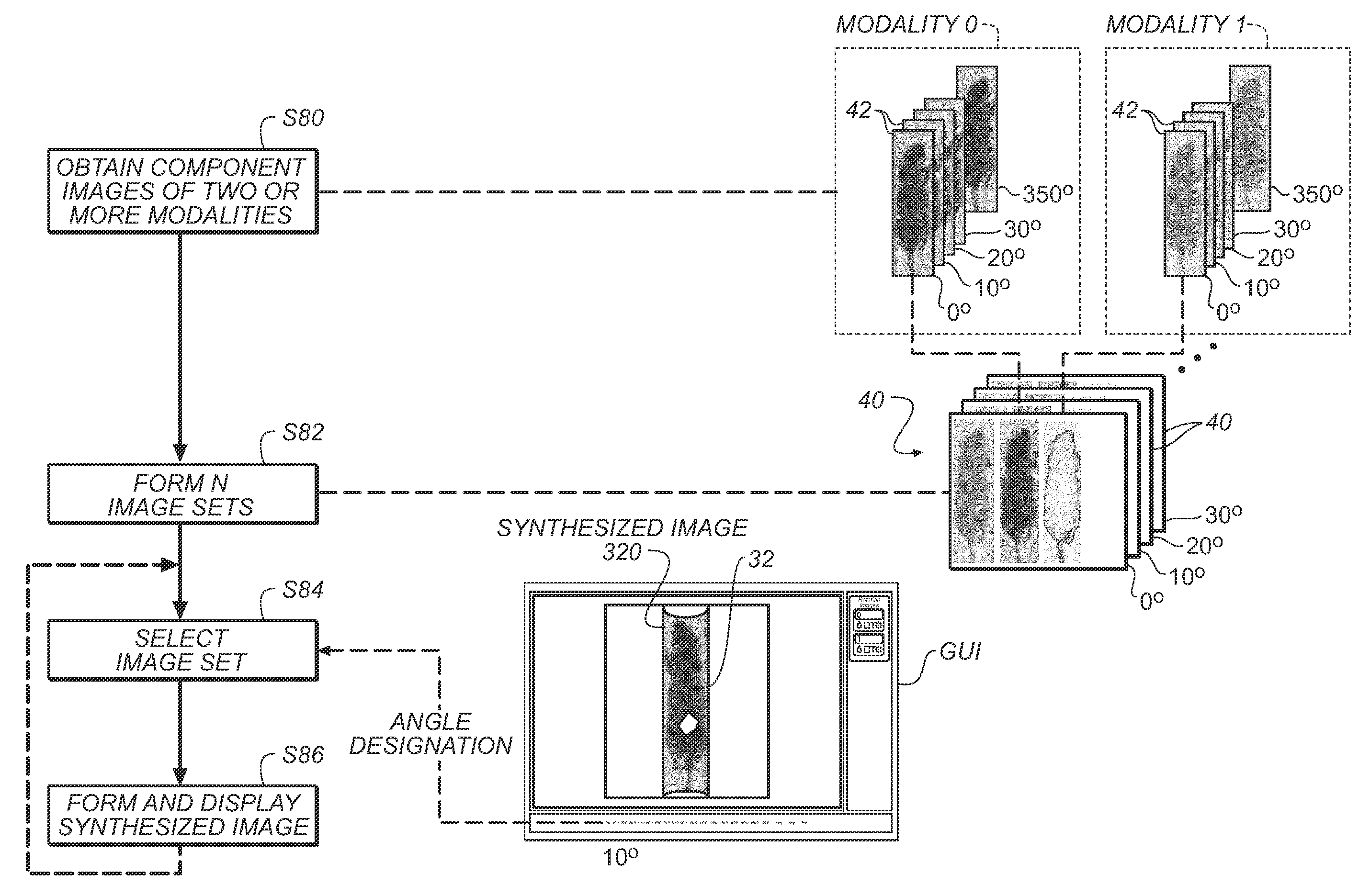
Graphical user interface for multi-modal images at incremental angular displacements
a multi-modal imaging and user interface technology, applied in the field of multi-modal imaging of objects, can solve the problems of cumbersome image display tools, requiring significant manual interaction, command entry and manipulation, and conventional tools failing to take advantage of multi-modal imaging apparatus features, etc., and achieve the effect of convenient viewing
- Summary
- Abstract
- Description
- Claims
- Application Information
AI Technical Summary
Benefits of technology
Problems solved by technology
Method used
Image

Examples
Embodiment Construction
[0058]The invention is described in detail with particular reference to certain preferred embodiments thereof, but it will be understood that variations and modifications can be effected within the spirit and scope of the invention. The following is a detailed description of the preferred embodiments of the invention, reference being made to the drawings in which the same reference numerals identify the same elements of structure in each of the several figures.
[0059]As used herein, the terms “zeroeth”, “first”, “second”, and so on, do not necessarily denote any ordinal or priority relation, but may be simply used to more clearly distinguish one element from another.
[0060]The term “modality” or, alternately, “diagnostic modality” relates to the type of imaging that is used in order to obtain a diagnostic image. For example, x-ray imaging is one imaging modality; fluorescence imaging is another modality. A synthesized image is a “composite” image that is formed from two or more “compo...
PUM
 Abstract
Description
Claims
Application Information