Refrigeration apparatus for refrigeration appliance and method of minimizing frost accumulation

a technology of refrigeration appliances and refrigeration equipment, which is applied in the field of refrigeration appliances, can solve the problems of affecting the practicability of placing ice makers in the freezer compartment, and affecting the operation of such ice makers, so as to achieve the effect of minimizing the introduction of air back

Active Publication Date: 2010-09-02
ELECTROLUX HOME PROD CORP NV
View PDF54 Cites 3 Cited by
  • Summary
  • Abstract
  • Description
  • Claims
  • Application Information

AI Technical Summary

Benefits of technology

[0010]According to one aspect, the subject application involves a refrigeration appliance including a fresh food compartment for storing food items in a refrigerated environment having a target temperature above zero degrees Centigrade, and a freezer compartment disposed at an elevation vertically below the fresh food compartment for storing food items in a sub-freezing environment having a target temperature below zero degrees Centigrade. A return air duct extends between the fresh food compartment and the freezer compartment for introducing air returning from the fresh food compartment into the freezer compartment adjacent a lateral boundary of the freezer compartment. A refrigeration system is operable to provide a cooling effect to the freezer compartment. The refrigeration system includes an evaporator in thermal communication with the freezer compartment. A bracket couples the evaporator to the refrigeration appliance, and includes an air barrier extending between the air duct and a bottom portion of the evaporator to minimize introduction of air returning from the fresh food compartment to a lateral side portion of the evaporator.
[0012]According to another aspect, the subject application involves a refrigeration appliance that includes a fresh food compartment for storing food items in a refrigerated environment having a target temperature above zero degrees Centigrade, and a freezer compartment disposed at an elevation vertically below the fresh food compartment for storing food items in a sub-freezing environment having a target temperature below zero degrees Centigrade. A refrigeration system is operable to provide a cooling effect to the freezer compartment, the refrigeration system comprising an evaporator in thermal communication with the freezer compartment. The evaporator includes a bottom portion supported above a floor of the freezer compartment and two laterally spaced sides. An air barrier is provided adjacent to at least one of the lateral sides of the evaporator for minimizing introduction of return air returning from the fresh food compartment to the evaporator along the at least one of the lateral sides. A heater is operable to provide a heating effect to melt frost accumulated on the at least one lateral side of the evaporator adjacent the air barrier and the bottom portion of the evaporator to melt.

Problems solved by technology

However, for refrigerators such as the so-called“bottom mount” refrigerator, which includes a freezer compartment disposed vertically beneath a fresh food compartment, placing the ice maker within the freezer compartment is impractical.
Thus, ice makers are commonly included in the fresh food compartment of bottom mount refrigerators, which creates many challenges in making and storing ice within a compartment that is typically maintained above the freezing temperature of water.
Operation of such ice makers may be affected by temperature fluctuations and other events occurring within the fresh food compartments housing the ice makers, and prolonged exposure of the ice to the ambient environment of the fresh food compartment can result in partial melting of ice pieces.
Further, assembly of such refrigerators can be complex and labor intensive due in part to the measures that must be taken to store ice pieces within the fresh food compartment.

Method used


Image

  • Refrigeration apparatus for refrigeration appliance and method of minimizing frost accumulation
  • Refrigeration apparatus for refrigeration appliance and method of minimizing frost accumulation
  • Refrigeration apparatus for refrigeration appliance and method of minimizing frost accumulation

Examples


Embodiment Construction

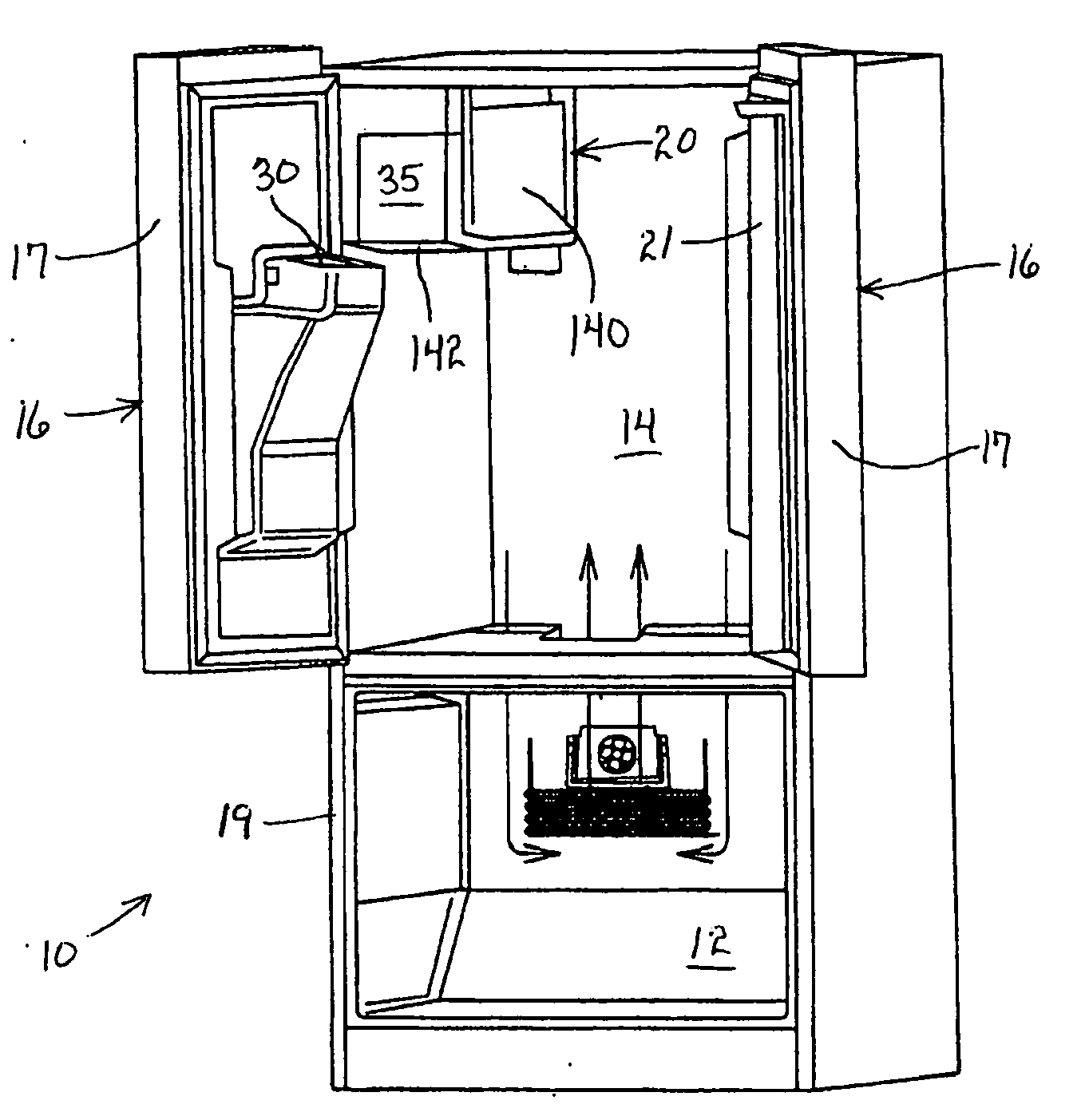
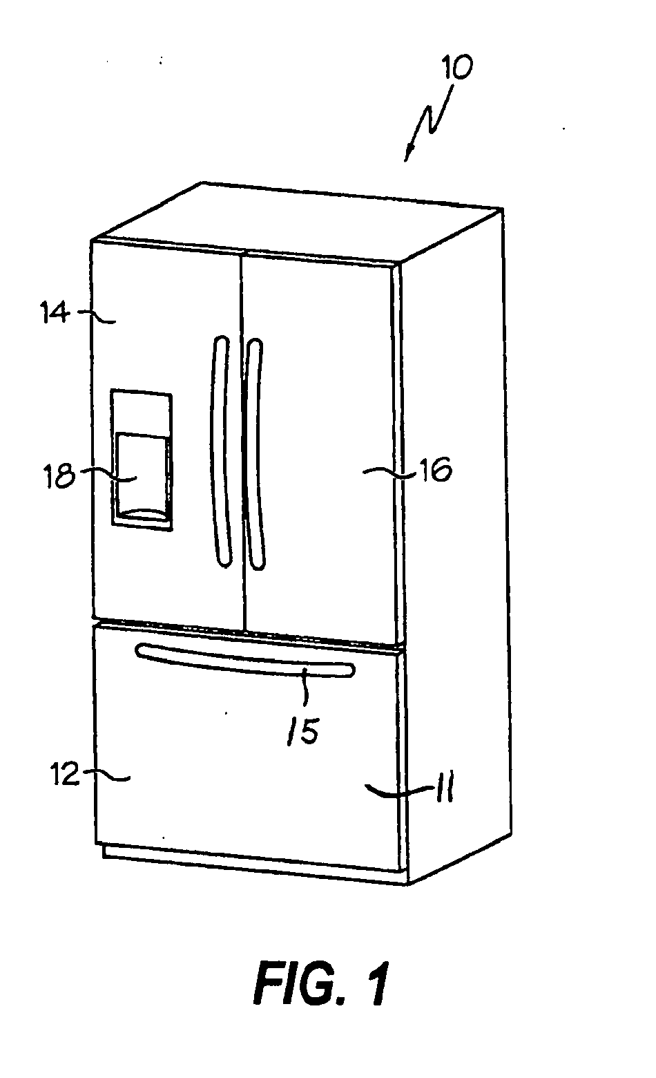
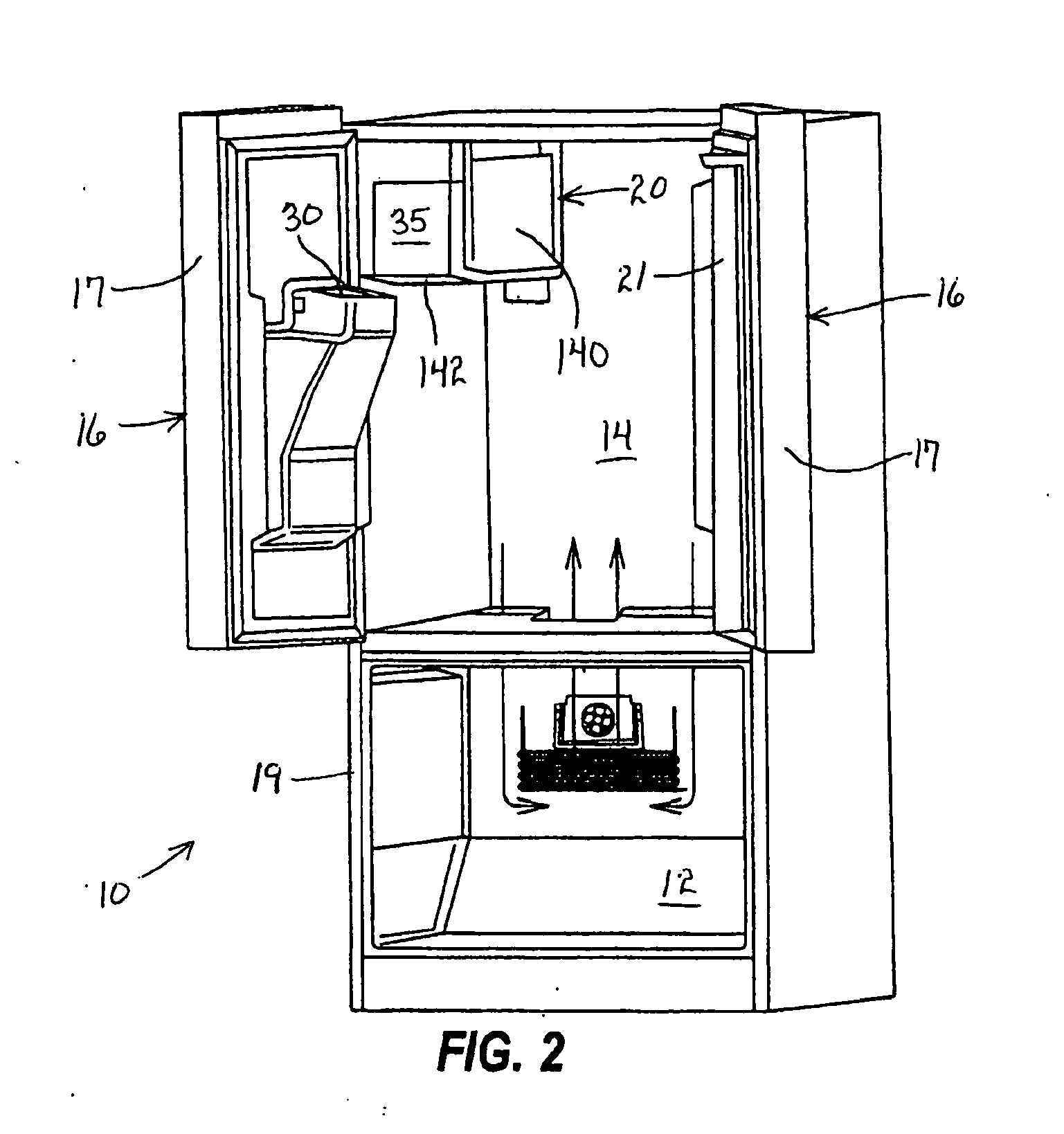
[0049]Certain terminology is used herein for convenience only and is not to be taken as a limitation on the present invention. Relative language used herein is best understood with reference to the drawings, in which like numerals are used to identify like or similar items. Further, in the drawings, certain features may be shown in somewhat schematic form.

[0050]It is also to be noted that the phrase “at least one of”, if used herein, followed by a plurality of members herein means one of the members, or a combination of more than one of the members. For example, the phrase “at least one of a first widget and a second widget” means in the present application: the first widget, the second widget, or the first widget and the second widget. Likewise, “at least one of a first widget, a second widget and a third widget” means in the present application: the first widget, the second widget, the third widget, the first widget and the second widget, the first widget and the third widget, the...


PUM

PropertyMeasurementUnit
temperatureaaaaaaaaaa
temperaturesaaaaaaaaaa
temperatureaaaaaaaaaa

Abstract

Provided is a refrigeration appliance including a fresh food compartment for storing food items in a refrigerated environment having a target temperature above zero degrees Centigrade, and a freezer compartment disposed vertically below the fresh food compartment for storing food items below zero degrees Centigrade. A return air duct returns air from the fresh food compartment to the freezer compartment, and a bracket supporting an evaporator includes an air barrier extending between the air duct and a bottom portion of the evaporator to minimize introduction of air returning from the fresh food compartment to a lateral side portion of the evaporator. A fan is rotatable about an axis having a substantially-horizontal orientation to circulate air, and a heater extends along a bottom portion, and beyond the lateral extents of the bottom portion of the evaporator in an upward direction along lateral sides of the evaporator.

Description

CROSS-REFERENCE TO RELATED APPLICATIONS[0001]This application claims the benefit of U.S. Provisional Application No. 61 / 156,501, filed Feb. 28, 2009, which is incorporated in its entirety herein by reference.BACKGROUND OF THE INVENTION[0002]1. Field of the Invention[0003]This application relates generally to an ice making appliance, and more specifically to a refrigeration appliance including an ice maker disposed within a food-storage compartment of a refrigerator that is maintained at a temperature above a freezing temperature of water at atmospheric conditions, and a method of controlling the ice maker to produce ice.[0004]2. Description of Related Art[0005]Conventional refrigeration appliances, such as domestic refrigerators, typically have both a fresh food compartment and a freezer compartment or section. The fresh food compartment is where food items such as fruits, vegetables, and beverages are stored and the freezer compartment is where food items that are to be kept in a f...

Claims


Application Information

Patent Timeline
Patent Type & Authority Applications(United States)
IPC IPC(8): F25D21/08F25D13/04F25D17/04
CPCF25B2700/02Y10T74/2107F25C5/005F25C5/08F25C5/187F25C2400/10F25C2500/06F25C2600/04F25C2700/12F25D11/022F25D17/065F25D21/04F25D21/14F25D23/066F25D2317/0651F25D2317/0661F25D2317/0666F25D2317/067F25D2317/0681F25D2323/021F25D2400/40F25D2700/10Y10T74/2101Y10T29/49826F25C1/08F25B47/02F25D11/02F25D23/12F25D2321/1413Y10T137/85938F25C5/22
Inventor CANDEO, MARCELO
Owner ELECTROLUX HOME PROD CORP NV
Why Eureka
Try Eureka