Fluid powered additive injection system

a technology of additive injection and fluid, which is applied in the direction of positive displacement liquid engines, piston pumps, instruments, etc., can solve the problems and achieve the effect of slowing down the prime mover speed and minimizing the introduction of air into the system

Active Publication Date: 2006-06-27
HAMMONDS TECHN SERVICES
View PDF17 Cites 20 Cited by
  • Summary
  • Abstract
  • Description
  • Claims
  • Application Information

AI Technical Summary

Benefits of technology

[0014]Another object of the invention is to provide a positive-displacement proportional chemical injection system having an injection pump immersed in the chemical additive to minimize introduction of air into the system.
[0015]Another object of the invention is to provide a positive-displacement proportional chemical injection system wherein the ratio adjustment is easily made by a user of the system.SUMMARY OF THE INVENTION
[0017]A flow restrictor or throttle valve is located adjacent the control valve to limit the energy of the fluid flowing to the hydraulic prime mover, resulting in slower prime mover speed.
[0018]The metering pump is optimally immersed in the chemical additive to minimize introduction of air into the system. A check valve located at the output of the metering pump prohibits flow reversing through the metering pump when the pump is idle or between pump cycles.

Problems solved by technology

A flow restrictor or throttle valve is located adjacent the control valve to limit the energy of the fluid flowing to the hydraulic prime mover, resulting in slower prime mover speed.

Method used


Image

  • Fluid powered additive injection system
  • Fluid powered additive injection system
  • Fluid powered additive injection system

Examples


Embodiment Construction

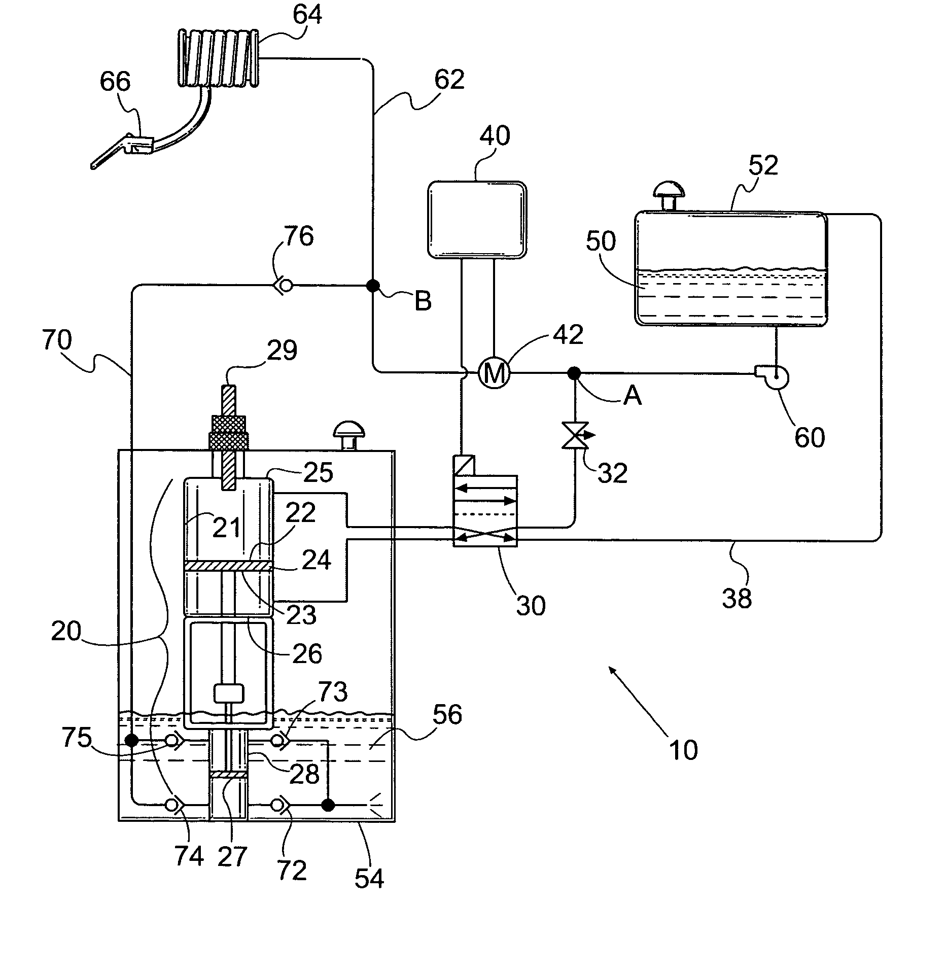
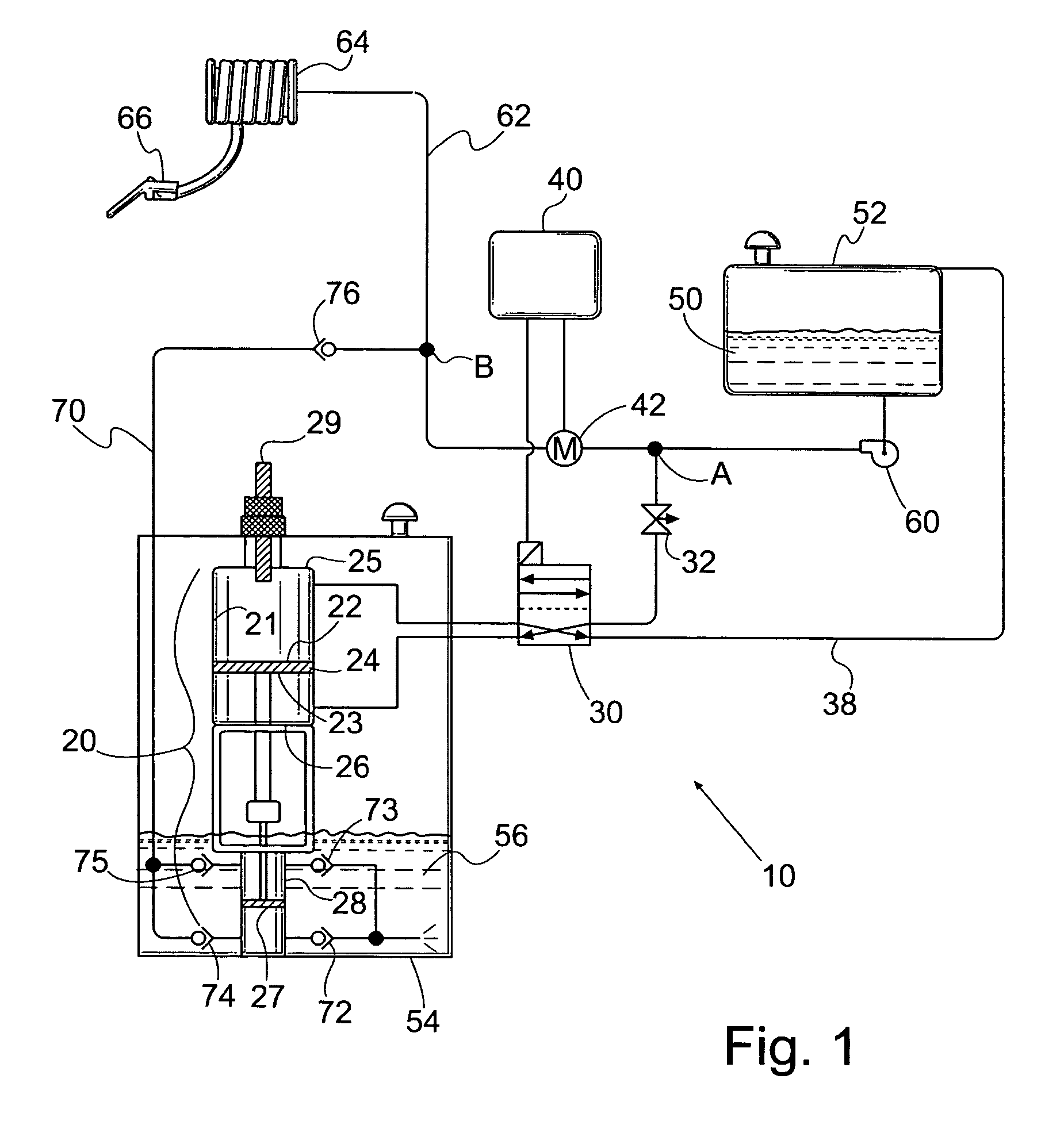
[0025]As illustrated in FIG. 1, the additive injection system 10 according to the invention comprises a master-slave piston pump arrangement 20, an electrically actuated control valve 30 for porting fluid to reciprocate the piston pump, and a controller 40 with a flow meter 42 which together operate the control valve 30 at a rate based on flow in the system to which the chemicals are to be added. The piston pump arrangement includes a power cylinder 21 with master piston 24 attached to a smaller injection cylinder 28 with plunger 27. The master piston 24 is dynamically sealed with the power cylinder 21, and the injection plunger is dynamically sealed within the injection cylinder 28.

[0026]The master-slave piston pump 20 is designed and arranged to be immersed in the chemical additive 56 within the chemical addition storage tank 54. Although not necessary, it is advantageous for master-slave pump 20 to be located in tank 54 because immersion reduces the likelihood of air being induce...


PUM


Abstract

An apparatus and method for proportionally injecting a liquid chemical into a fluid stream using a portion of the fluid stream as motive force for a chemical injection pump. The apparatus includes a paired single or double acting reciprocating injection pump and driver with the driver piston(s) having a surface area of three times the surface area of the injection piston(s). The portion of the fluid stream is passed through a prime mover to the pump and then discharged to atmosphere. A fluid product flow meter generates a signal which controls the cycling of the reciprocating pump.

Description

CROSS REFERENCE TO RELATED APPLICATION[0001]This application is based upon provisional application 60 / 425,108 filed on Nov. 7, 2002, the priority of which is claimed.BACKGROUND OF THE INVENTION[0002]1. Field of the Invention[0003]This invention relates generally to the field of additive pumps that inject a chemical additive such as a dye, de-icing agent, detergent or the like into a liquid flow stream and specifically to a method and apparatus for powering an additive metering pump from the pressure head of said liquid flow stream and controlling it for proportionality.[0004]2. Description of the Prior Art[0005]A popular means of injecting chemical additives into various liquid streams, particularly fuels, is to use a signal generated from a flow meter in the recipient line to control a chemical injection pump. Most flow meters used for this purpose generate a discrete pulse as a given volume of fluid has flowed through the meter as opposed to providing a continuous signal whose amp...

Claims


Application Information

Patent Timeline
Patent Type & Authority Patents(United States)
IPC IPC(8): B67D5/08B67D7/08F04B9/02F04B9/113F04B9/117F04B13/02G05D11/00
CPCF04B9/02F04B9/113G05D11/006F04B13/02F04B9/1172G05D11/131
Inventor HAMMONDS, CARL L.
Owner HAMMONDS TECHN SERVICES
Why Eureka
Try Eureka