Brake apparatus brake control apparatus, and brake control method

a technology of brake control apparatus and brake control, which is applied in the direction of braking system, instruments, analogue processes for specific applications, etc., can solve the problems of insufficient pedal feeling, inability to open the valve, and simulator cannot function sufficiently well, so as to reduce power consumption and facilitate control the effect of the switch valv

Inactive Publication Date: 2010-09-02
TOYOTA JIDOSHA KK
View PDF9 Cites 15 Cited by
  • Summary
  • Abstract
  • Description
  • Claims
  • Application Information

AI Technical Summary

Benefits of technology

[0008]In consideration of the problems described above, the present invention provides a brake control technique for a brake apparatus including a switch valve that is driven steadily by applying a steady-state current thereto, with which a reduction in power consumption can be achieved while maintaining favorable control responsiveness in the switch valve at all times.

Problems solved by technology

When the switch valve temporarily closes in this manner, it may be impossible to open the valve using the valve opening characteristic described above by applying the steady-state current alone.
In a case where a simulator cut valve is closed in this manner, for example, a stroke simulator cannot function sufficiently well when the driver depresses the brake pedal, and as a result, the pedal feeling deteriorates.
Further, when an isolation valve is closed in this manner in a case where vehicle travel control is performed automatically, for example, the required working fluid is not supplied to the respective wheels, leading to deterioration of the control performance.
With respect to a normally open switch valve, on the other hand, the valve is operated in a closing direction by the activation current and maintained in a closed state by the subsequent steady-state current, but when the valve opens due to a temporary voltage reduction, as described above, similar problems may occur.

Method used


Image

  • Brake apparatus brake control apparatus, and brake control method
  • Brake apparatus brake control apparatus, and brake control method
  • Brake apparatus brake control apparatus, and brake control method

Examples


first embodiment

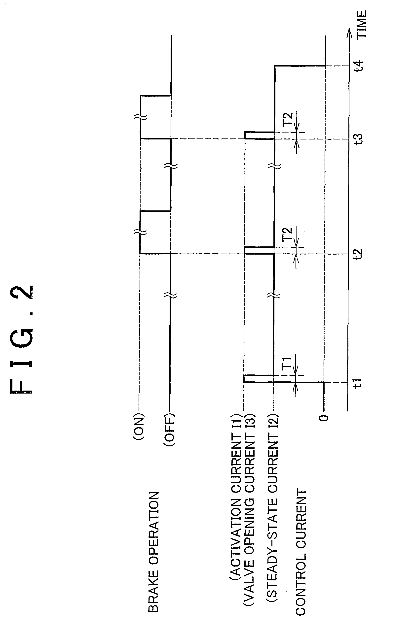
[0106]In the first embodiment described above, an example in which the valve opening current I3 is applied every time the brake pedal 24 is depressed was described. Strictly speaking, however, a temporal delay occurs in the control current as it rises to the target value, and therefore a command to supply the valve opening current I3 is preferably issued immediately before the brake pedal 24 is depressed such that the valve opening current I3 is applied at the time of the actual depression. On the other hand, depression of the brake pedal 24 depends on the will of the driver, and comprehending the will of the driver on the brake ECU 70 side is difficult. Hence, in this embodiment, a command to supply the valve opening current I3 is output at a preset timing during the application period of the steady-state current I2. In so doing, the valve opening current I3 is more likely to be supplied when the brake pedal 24 is depressed.

[0107]More specifically, in the example shown in the drawi...

fifth embodiment

[0134]FIG. 9 is an illustrative view showing electrification control according to the The drawing shows a case corresponding to FIG. 8B, in which the brake pedal 24 is depressed rapidly. The brake stroke, the regulator pressure Preg, and the current command signal are shown in order from the upper section of the drawing, and the abscissa represents the passage of time.

[0135]In this embodiment, as shown in the drawing, a determination reference for determining depression of the brake pedal 24 when rapid depression is performed is set at a brake stroke S2 (3 mm, for example) that is smaller than the reference brake stroke S0 serving as the determination reference during a normal period when rapid depression is not performed. Note that here, it is determined that rapid depression has been performed when temporal variation in the brake stroke immediately after depression of the brake pedal 24, temporal variation in the regulator pressure Preg, or similar is larger than a predetermined ...

sixth embodiment

[0139]FIG. 10 is an illustrative view showing electrification control according to the The drawing shows a case corresponding to FIG. 9, in which the brake pedal 24 is depressed rapidly. The brake stroke, the regulator pressure Preg, and the current command signal are shown in order from the upper section of the drawing, and the abscissa represents the passage of time.

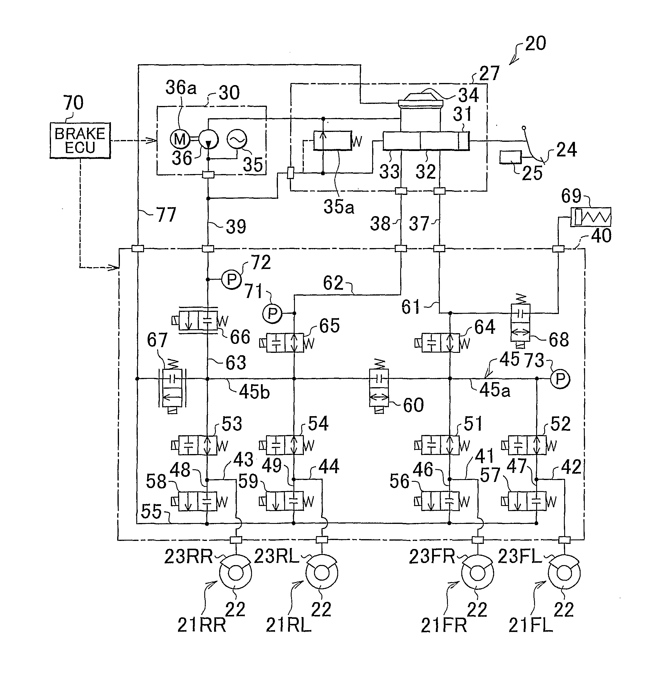
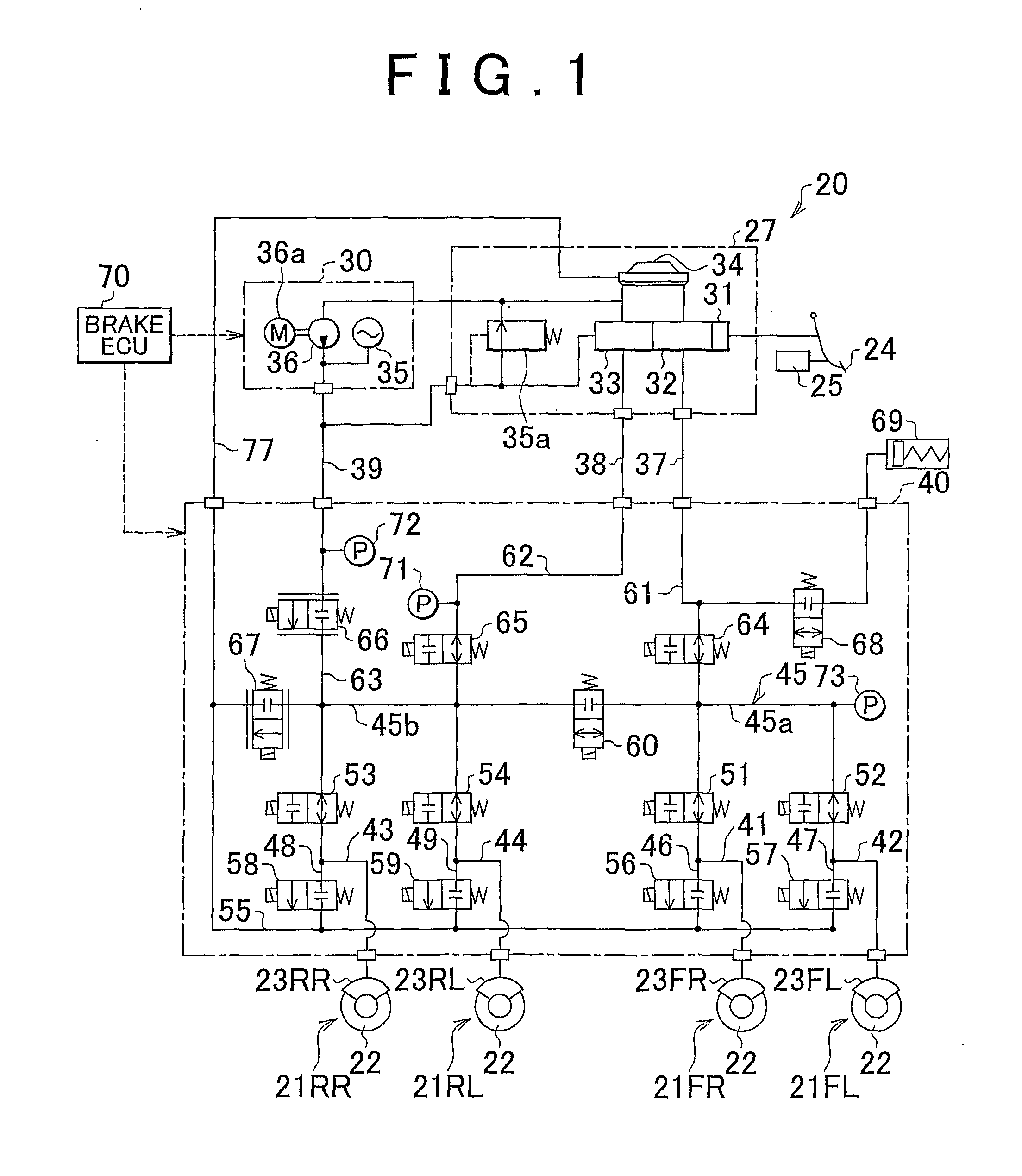
[0140]In this embodiment, as shown in the drawing, the rise time of the regulator pressure Preg is set as the determination reference for determining depression of the brake pedal 24. More specifically, in this embodiment, it is determined that the brake pedal 24 has been depressed when the hydraulic pressure of the master channel 61, which rises more quickly than that of the main channel 45, increases rather than the hydraulic pressure in both the main channel 45 and the master channel 61.

[0141]Here, a command signal for switching to the valve opening current I3 is output at a time t52, i.e. the rise time of the regu...


PUM


Abstract

In a brake apparatus, an activation current for opening a simulator cut valve from a closed state is applied, whereupon a steady-state current is applied continuously to maintain the open state. A brake control apparatus and a brake control method are employed to perform control in which a valve opening current, which is higher than the steady-state current, is applied to the simulator cut valve every time a brake pedal is depressed. Thus, in a brake apparatus including a switch valve that is driven steadily by applying the steady-state current thereto, favorable control responsiveness can be maintained in the switch valve at all times while achieving a reduction in power consumption.

Description

BACKGROUND OF THE INVENTION[0001]1. Field of the Invention[0002]The present invention relates to brake control for controlling a braking force applied to a wheel of a vehicle.[0003]2. Description of the Related Art[0004]A brake apparatus that generates hydraulic pressure corresponding to an operation of a brake pedal in a hydraulic circuit and applies a braking force to a wheel by supplying the hydraulic pressure to a wheel cylinder is conventionally available. A plurality of electromagnetic valves are provided in the hydraulic circuit, and by open / close controlling each electromagnetic valve so as to adjust supply / discharge amounts of a working fluid to / from the wheel cylinder, the hydraulic pressure is controlled such that an appropriate braking force is applied to each wheel.[0005]This type of electromagnetic valve includes an electromagnetic valve that is maintained in a driven state by applying a steady-state current, which is lower than an activation current, thereto steadily ...

Claims


Application Information

Patent Timeline
Patent Type & Authority Applications(United States)
IPC IPC(8): B60T11/10F16D55/22B60T17/00B60T11/28G06F19/00B60T8/17
CPCB60T8/4081B60T8/36
Inventor FUKASAWA, TSUKASAOKANO, TAKAHIRONAKATA, DAISUKENAKAMURA, EIJI
Owner TOYOTA JIDOSHA KK
Why Eureka
Try Eureka