Electronic apparatus

a technology of electronic equipment and forming molds, applied in the direction of emergency actuators, switches with three operating positions, contact mechanisms, etc., can solve the problems of complex structure of forming molds, high precision of every component, and not easy to manufacture, etc., and achieve the effect of simple structure and easy manufacturing

Inactive Publication Date: 2010-09-02
PANASONIC CORP
View PDF13 Cites 13 Cited by
  • Summary
  • Abstract
  • Description
  • Claims
  • Application Information

AI Technical Summary

Benefits of technology

[0006]A purpose of the invention made in the above-mentioned background is to provide an electronic

Problems solved by technology

In the conventional electronic apparatus, however, since the tilt structure is made up of the pivot portion 111 and its bearing portion

Method used


Image

  • Electronic apparatus
  • Electronic apparatus
  • Electronic apparatus

Examples


Embodiment Construction

[0042]Now, the invention will be described in detail. However, the following detailed description and appended drawings are not intended to limit the invention. Rather, the scope of the invention is defined by the appended claims.

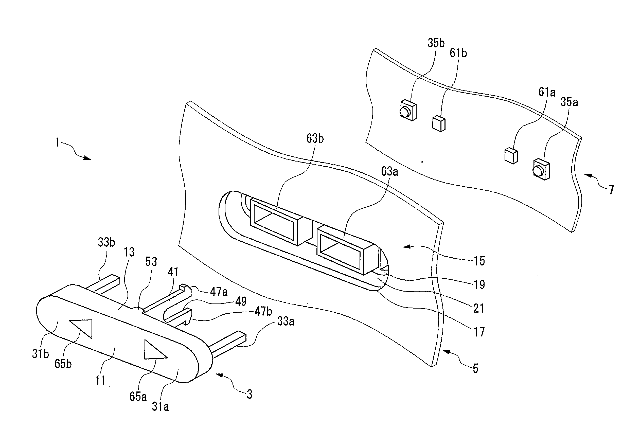
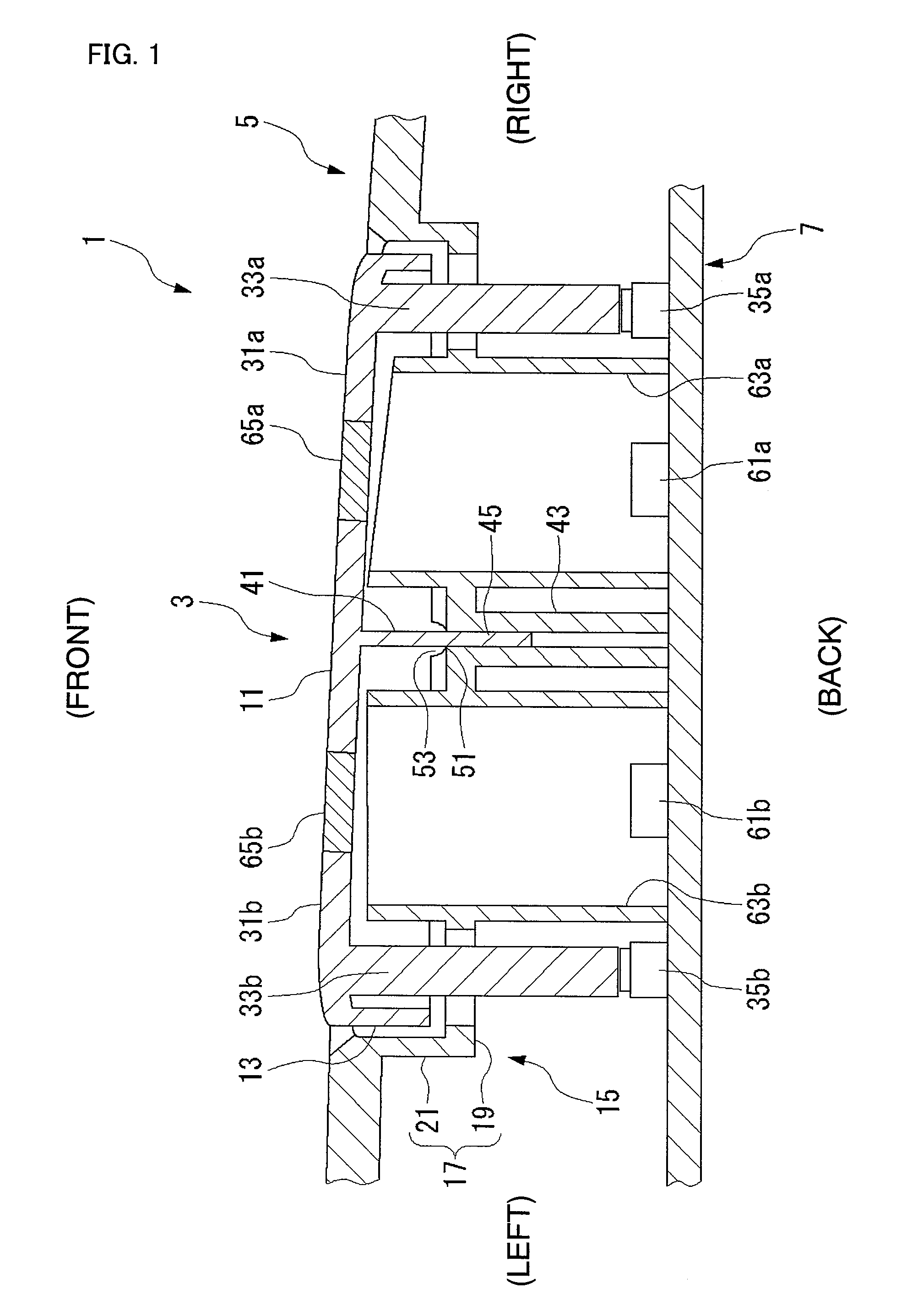
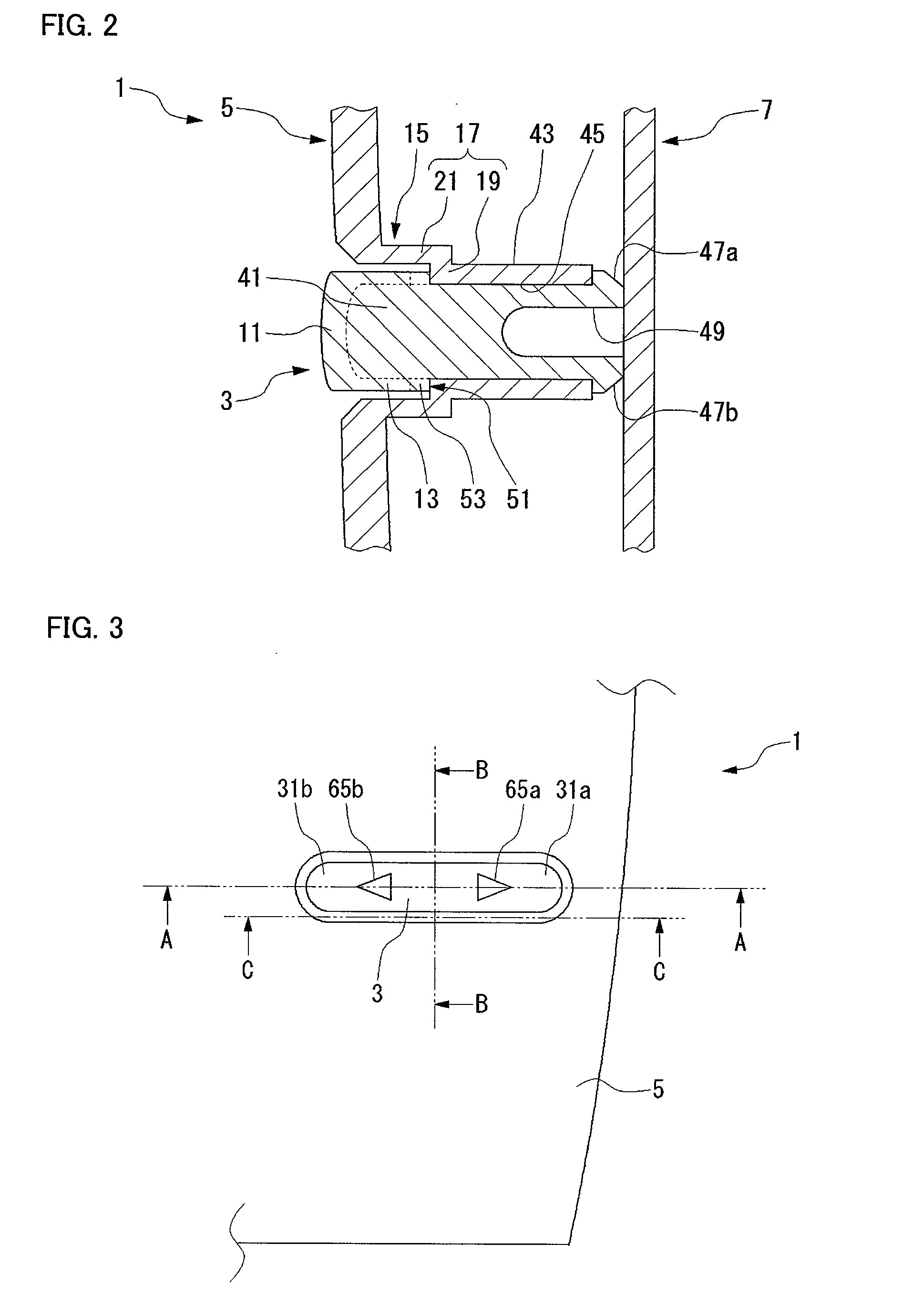
[0043]An electronic apparatus of the invention has: an operation button; an operation panel provided with a holding portion for holding the operation button; and a plurality of switches to be pushed down by the operation button, wherein the operation button includes: a plurality of operating portions; a plurality of pressing portions respectively provided on the plurality of operating portions toward the plurality of switches; and a flat-shaped flexible board portion protruded between the plurality of pressing portions, the board portion of the operation button for being held by the holding portion.

[0044]In this configuration, the board portion of the operation button is held by the holding portion of the operation panel. The board portion bends and functio...


PUM


Abstract

The structure of an electronic apparatus (1) is simplified to facilitate its production, where the apparatus has a seesaw type operation button tiltable in multiple directions. The electronic apparatus (1) has the operation button (3), an operation panel (5) where a holding section (15) for holding the operation button (3) is provided, and switches (35a, 35b) pressed down by the operation button (3). The operation button (3) has operation sections (31a, 31b), pressing sections (33a, 33b) individually provided at the operation sections (31a, 31b), toward the switches (35a, 35b), and a flexible flat plate section (41) projected between the pressing sections (33a, 33b). The plate section (41) is held by the holding section (15).

Description

TECHNICAL FIELD[0001]The present invention relates to an electronic apparatus provided with a seesaw-type operation button.BACKGROUND ART[0002]Conventional car audio equipment or other electronic apparatuses often have a seesaw-type operation button. FIGS. 11 and 12 show a conventional example, electronic apparatus 101. The electronic apparatus 101 comprises an operation button 103, a button holding member 105, and a substrate 107. The operation button 103 is held by the button holding member 105 so as to be tiltable to both sides. When the operation button 103 tilts, a switch 109a or 109b on the substrate 107 is pushed. The switches 109a and 109b are provided on both sides of the tilt center of the operation button 103. A configuration of this type is disclosed, for example, in Japanese Patent Laid-Open Application No. 7-211195 (FIGS. 1 and 2).[0003]More particularly, the tilt structure of the operation button 103 is realized by a rotation structure comprising: a pivot portion 111 ...

Claims


Application Information

Patent Timeline
IPC IPC(8): H01H13/76
CPCH01H23/143H01H2221/044H01H2221/018H01H23/30
Inventor OKUZUMI, TOMOYA
Owner PANASONIC CORP
Why Eureka
Try Eureka