Apparatus with selectable functions
a selectable function and apparatus technology, applied in the field of apparatuses with selectable functions, can solve the problems of reducing the operability of electronic devices, affecting the user's experience, and reducing so as to reduce the number of input selection members, selectively perform functions, and reduce the number of operable members
- Summary
- Abstract
- Description
- Claims
- Application Information
AI Technical Summary
Benefits of technology
Problems solved by technology
Method used
Image
Examples
first embodiment
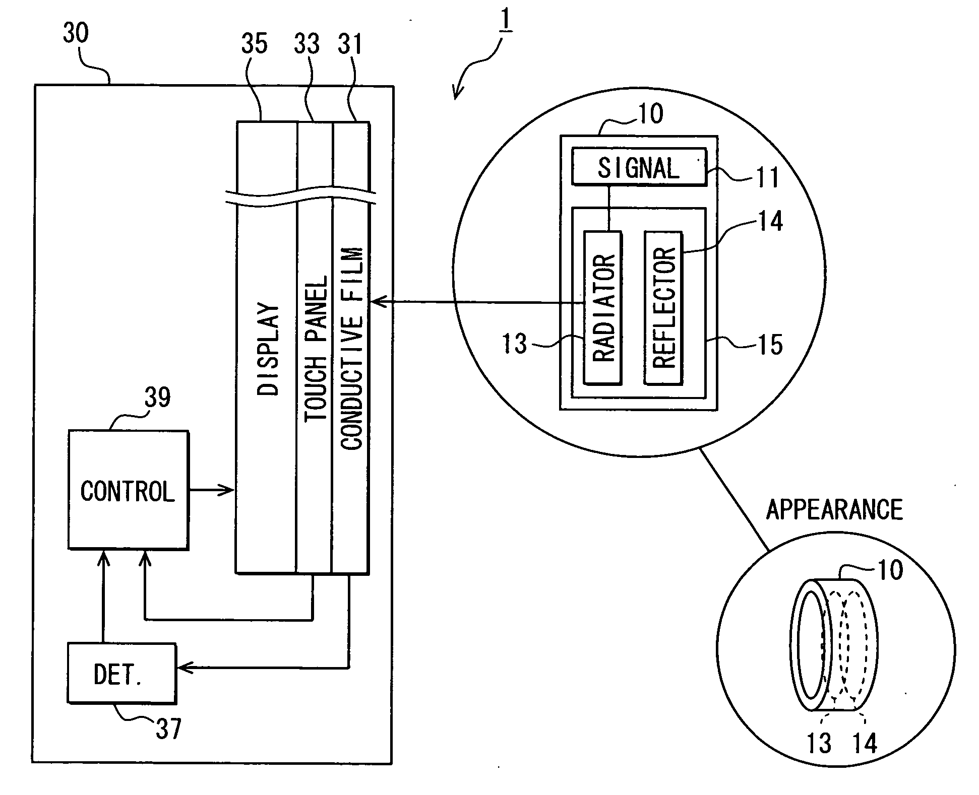
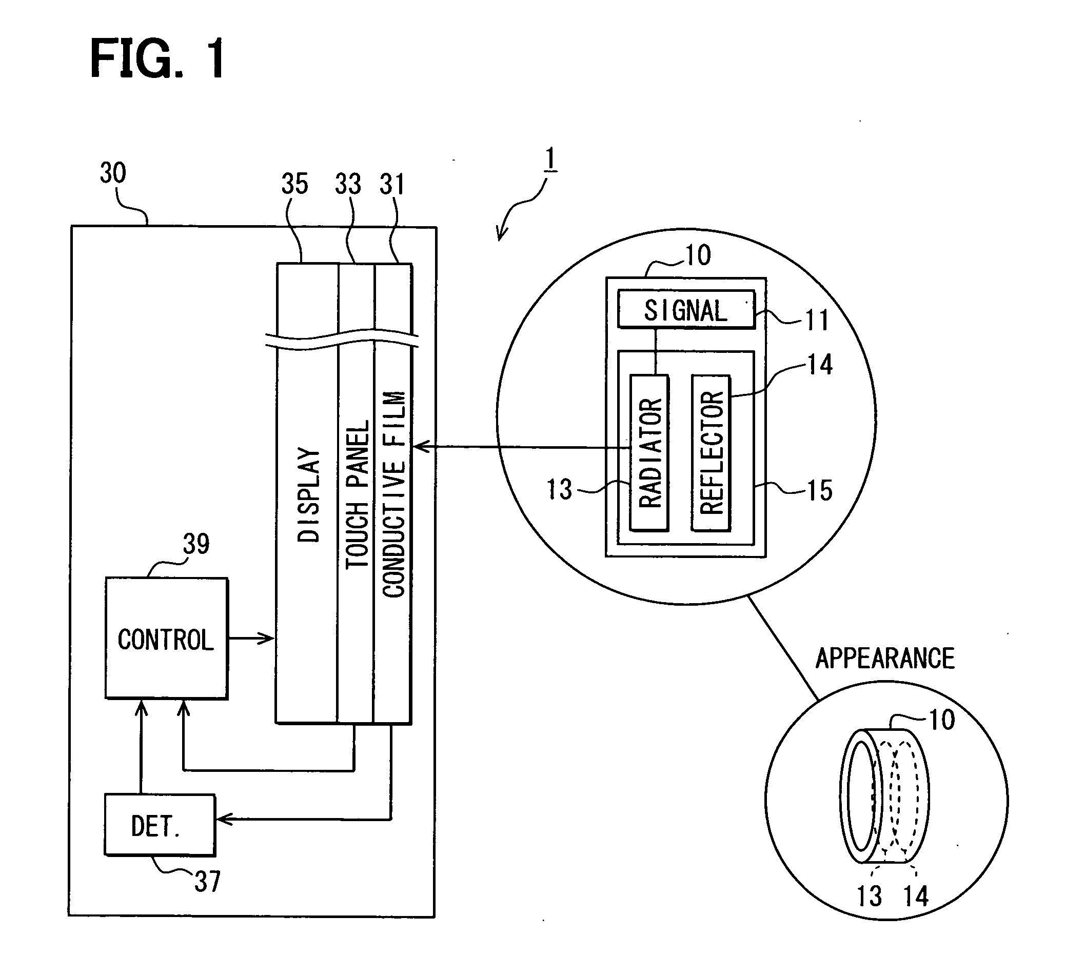
[0062]FIG. 1 is a block diagram showing an information processing system 1 including a user interface device. The information processing system 1 includes a transmitter module 10 and, an electronic device 30. The transmitter module 10 is formed in a wearable form, such as a ring. The transmitter module 10 may be referred to as a ring 10. The ring 10 outputs and supplies an electric signal to a body part on which the ring 10 is equipped. The electronic device 30 is operated by the user who wears the ring 10.
[0063]The ring 10 supplies the electric signal to the body part of the user by using an electric field. The electric signal is a weak radio wave. The ring 10 includes a transmitter circuit 11 and an antenna 15.
[0064]The antenna 15 is supplied with electric power from the transmitter circuit 11. The antenna 15 includes a radiator 13 for radiating the electric signal to the body part, and a reflector 14 which reflects the electric signal supplied from the radiator 13 to the body par...
second embodiment
[0092]An information processing system 1 according to a second embodiment is explained based on FIG. 5 and FIG. 6. The second embodiment has components shown in FIG. 1. FIG. 5 is a flow chart showing character input processing performed by the control unit 39. At the beginning of the character input processing, in S210, the control unit 39 displays the character input screen image for Hiragana input on the display device 35. The character input screen image for Hiragana input is referred to as a first input screen image VC1. FIG. 6A is a plan view of the first input screen image VC1. In this embodiment, a single character is assigned to each input object on the character input screen image.
[0093]In S220, the control unit 39 performs the processing described in S120. In S230, the control unit 39 performs the processing described in S160. In S240, the control unit 39 determines that whether a character input screen image for alphabet input is presently displayed on the display device ...
third embodiment
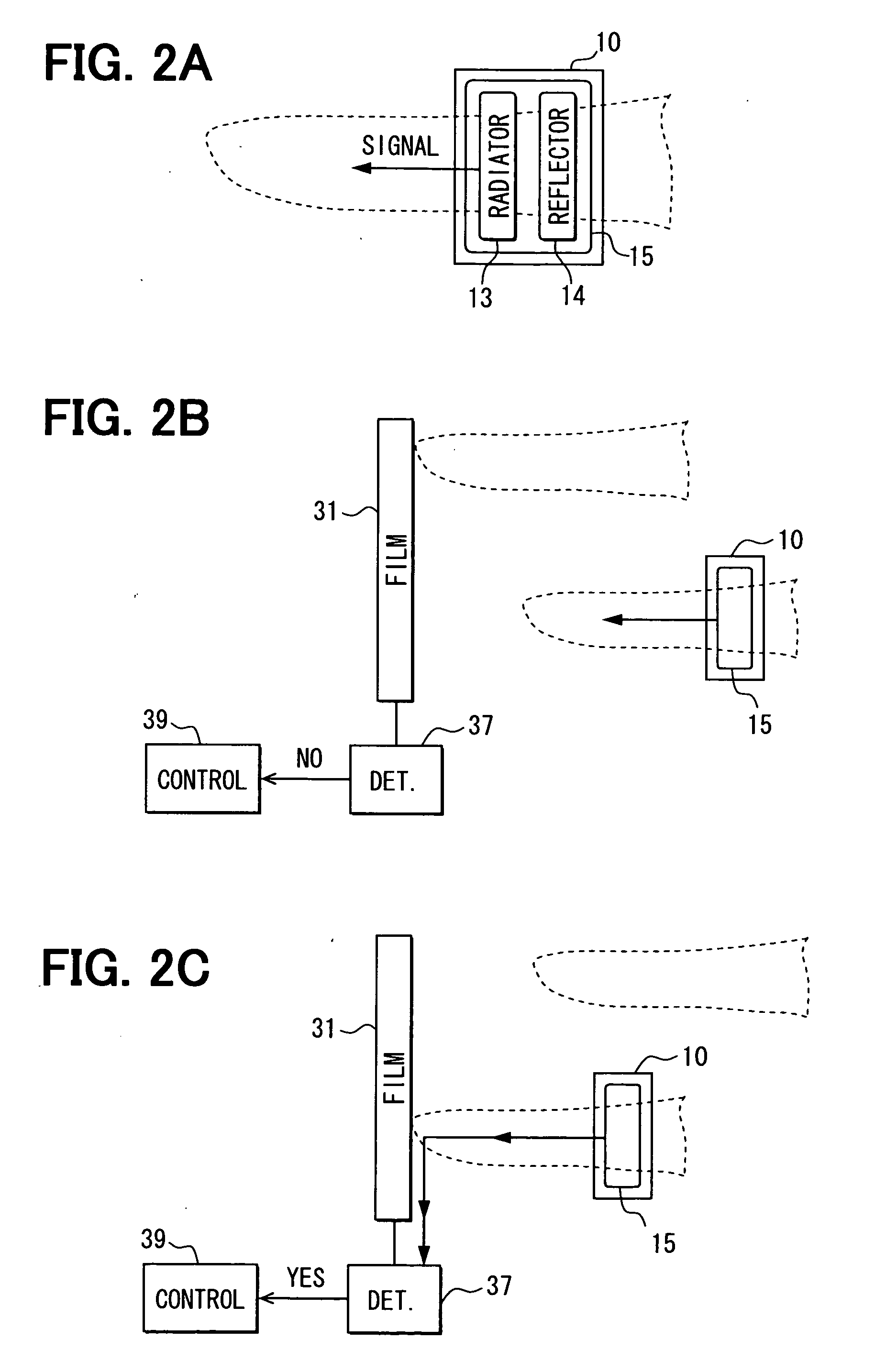
[0103]An information processing system 1 according to a third embodiment is explained based on FIG. 7. In the third embodiment, a threshold value in the signal detector 37 is adjusted to detect both a contact and proximity of the conductive film 31 and the body part on which the transmitter module 10 is equipped. FIG. 7 is a flow chart showing character input processing performed by the control unit 39. The processing in S210, S220, and S230 are described in the second embodiment. If the operation signal is not supplied from the touch panel 33, the control unit 39 proceeds the routine to S310. In S310, the control unit 39 determines that whether the YES signal is supplied from the signal detector 37 or not.
[0104]If the YES signal is supplied from the signal detector 37, the routine proceeds to “YES” from S310. In S320, the control unit 39 displays the second input screen image VC2 on the display device 35 instead of the first input screen image VC1, and, then, returns the routine to...
PUM
 Abstract
Description
Claims
Application Information
 - R&D
- Intellectual Property
- Life Sciences
- Materials
- Tech Scout
- Unparalleled Data Quality
- Higher Quality Content
- 60% Fewer Hallucinations
Browse by: Latest US Patents, China's latest patents, Technical Efficacy Thesaurus, Application Domain, Technology Topic, Popular Technical Reports.
© 2025 PatSnap. All rights reserved.Legal|Privacy policy|Modern Slavery Act Transparency Statement|Sitemap|About US| Contact US: help@patsnap.com


