
Sewing machine provided with needle bar rocking mechanism

a technology of needle bar and rocking mechanism, which is applied in the direction of needle bars, sewing machine elements, instruments, etc., can solve the problems of affecting the sewing operation, and affecting the sewing process

Active Publication Date: 2010-09-09
BROTHER KOGYO KK
View PDF8 Cites 14 Cited by
  • Summary
  • Abstract
  • Description
  • Claims
  • Application Information

AI Technical Summary

Benefits of technology

The patent text describes a sewing machine that has a needle bar with a needle attached, a mechanism to rock the needle bar, and a needle plate with a needle hole. The machine also has a camera to capture images of the needle bar and a computer program to analyze the images and set a range of motion for the needle bar. The machine can also have a button presser foot with multiple needle holes and a computer program to recognize the positions of the needle holes and set the rocking position of the needle bar to penetrate through the needle holes. The technical effect of this patent is to provide a sewing machine that can control the needle bar rocking mechanism to make the needle location appropriate for sewing.

Problems solved by technology

However, when a sewing machine body is subjected to a large impact such as by falling or a screw has been loosened in a mechanism, there is a possibility that the needle location may be displaced from a normal location.
Such displacement of the needle location may result in an undesirable sewing operation.
In a serous case, the needle would interfere with the needle plate with the result of breakage of the needle or the like.
However, the operator cannot visually determine the displacement of the needle location accurately (objectively).
As a result, affixing the reference mark is less reliable.
This indirect detecting manner results in a difficulty in an accurate detection of the rocking position of the needle relative to the needle hole.

Method used


Image

  • Sewing machine provided with needle bar rocking mechanism
  • Sewing machine provided with needle bar rocking mechanism
  • Sewing machine provided with needle bar rocking mechanism

Examples


Embodiment Construction

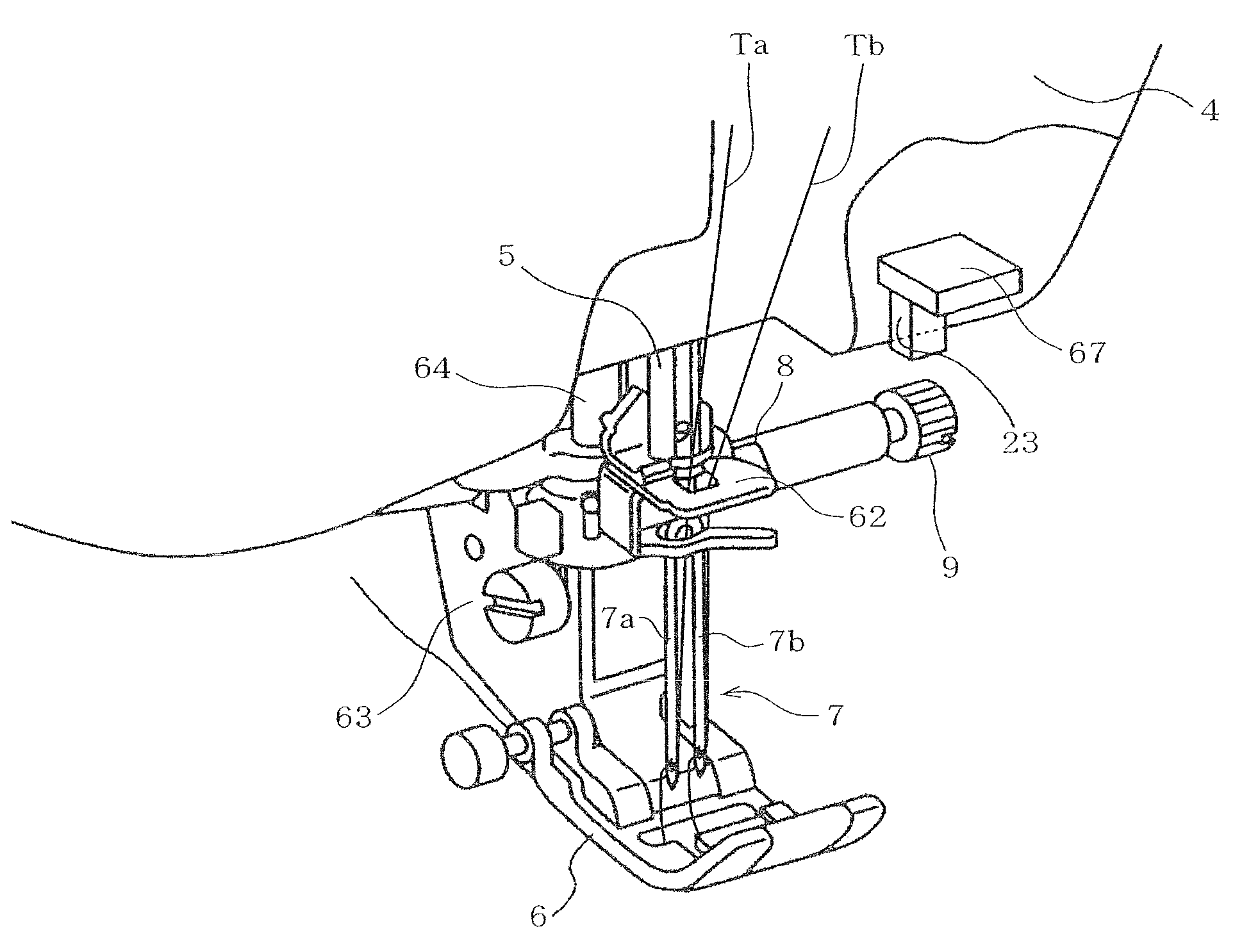
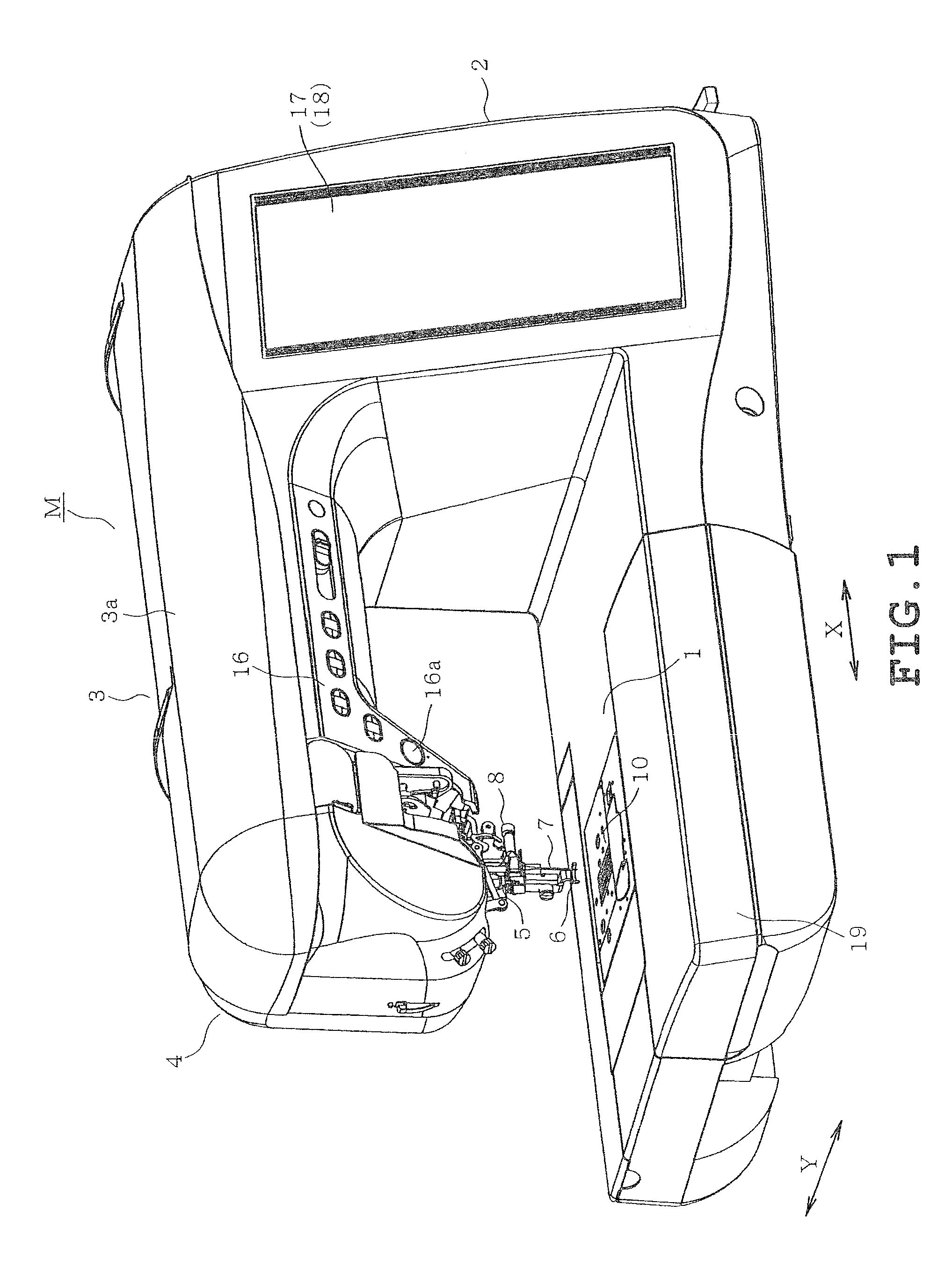
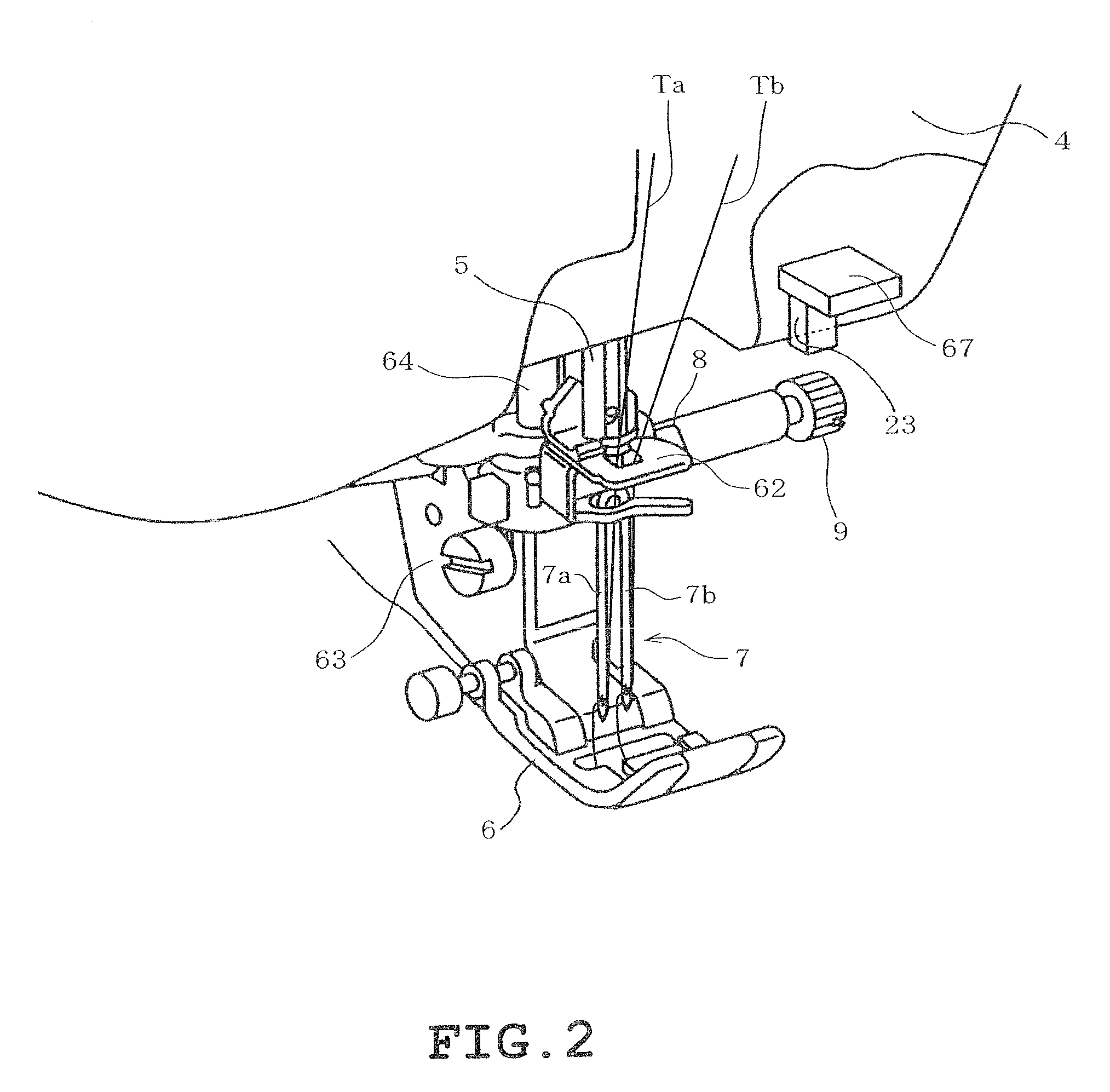
[0048]A first example of the present disclosure will be described with reference to FIGS. 1 to 11. Referring to FIG. 1, a sewing machine M includes a body which includes a sewing bed 1 extending in a right-left direction (X direction), a sewing pillar 2 extending upward from a right end of the bed 1 and a sewing arm 3 extending leftward from an upper end of the pillar 2, all of which are formed integrally. A sewing head 4 is mounted on a distal end of the arm 3. The bed 1 has an upper side on which a cover 3a is mounted so as to be openable and closable. The cover 3a covers a thread spool accommodating part (not shown) for accommodating a thread spool (not shown). In the following description, the user is assumed to be located at the front of the multineedle sewing machine M and the opposite side of the sewing machine will be referred to as “the rear.” Furthermore, the side of the sewing machine M where the pillar 2 is located will be referred to as “right” and the opposite side of ...


PUM


Abstract

A sewing machine includes a needle bar to which a needle is attached, a needle bar rocking mechanism which rocks the needle bar, a needle plate having a needle hole through which the needle is passed, an imaging device which images a lower part of the needle bar, a setting section which sets a range of rocking motion of the needle bar based on an image obtained by the imaging device, and a control device which controls the needle bar rocking mechanism based on the range of rocking motion set by the setting section.

Description

CROSS-REFERENCE TO RELATED APPLICATIONS[0001]This application is based upon and claims the benefit of priority from the prior Japanese Patent Application Nos. 2009-50004, 2009-50563 and 2009-50564 all filed on Mar. 4, 2009, the entire contents of which are incorporated herein by reference.BACKGROUND[0002]1. Technical Field[0003]The present disclosure relates to a sewing machine provided with a needle bar rocking mechanism which rocks a needle bar.[0004]2. Description of the Related Art[0005]Household sewing machines are generally provided with a needle bar rocking mechanism which is driven by a stepping motor serving as a drive source to rock a needle bar right and left, so that zigzag stitches can be formed on a workpiece cloth while the needle bar is rocked right and left. In this case, a needle plate is formed with a needle hole which is elongate in the right-left direction according to the rocking of the needle bar. Other than the zigzag stitches, the needle bar (a needle) is mo...

Claims


Application Information

Patent Timeline
Patent Type & Authority Applications(United States)
IPC IPC(8): D05B3/02D05B19/00D05B3/06D05B55/14
CPCD05B3/14D05B55/00D05B19/14
Inventor IHIRA, YUKIIWATA, MASAYUKIHIRATA, TAKASHI
Owner BROTHER KOGYO KK
Learn More