

Subterranean Screen with Varying Resistance to Flow
- Summary
- Abstract
- Description
- Claims
- Application Information
AI Technical Summary
Benefits of technology
Problems solved by technology
Method used
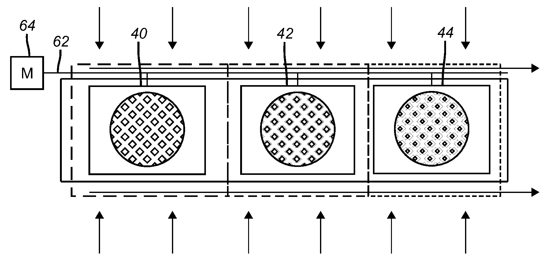
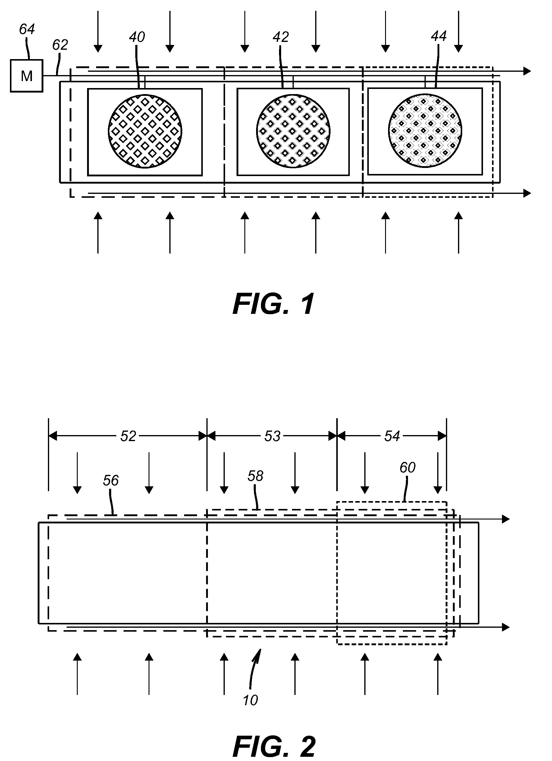
Image

Examples
Embodiment Construction
[0011]Starting first with FIGS. 5 and 6 there is illustrated a screen section 10 that is assembled into a string (not shown) for running into a subterranean formation (not shown). Typically screens come in sections of various lengths but usually about 10 meters long. Apart from end connections that are not shown between ends 12 and 14 there is a solid base pipe 16 that is closed at end 12 and which extends into a spiral path 18 before passing through one or more openings 20 to flow into passage 22 and to the surface when in production mode. When in injection mode the flow direction for the injection hot fluid, generally steam, is reversed.
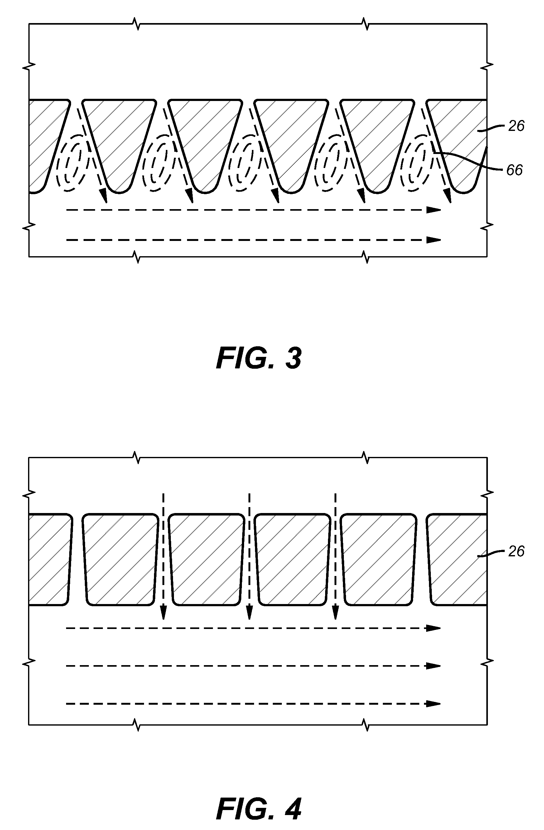
[0012]An annular flow space represented by arrow 24 is defined by a wire wrapped into a cylindrical shape 26 with a spiral wound gap 28 held at a relatively constant dimension by a plurality of ribs 30 welded or otherwise joined to the cylindrical shape 26. Overlayed on the cylindrical shape 26 is the screen assembly 32. In the illustrated embodime...
PUM
 Abstract
Description
Claims
Application Information