Homogeneous vent cap

Inactive Publication Date: 2006-01-12
HNI TECH INC
View PDF22 Cites 0 Cited by
  • Summary
  • Abstract
  • Description
  • Claims
  • Application Information

AI Technical Summary

Benefits of technology

[0007] The present invention relates to vent assemblies suited for use with a vent that includes intake and exhaust apertures. The vent assemblies are configured to provide proper fluid flow into and out of the respective intake and exhaust apertures of the vent, minimize the flow of fluids exhausted from the exhaust aperture into the intake aperture, and to improve the flow of intake air into the intake aperture.
[0011] A further aspect of the invention relates to a method of assembling a vent assembly that includes an exhaust member defining an exhaust aperture and an intake member defining an intake aperture. The method may include positioning a divider between the exhaust and intake apertures, positioning a flow guide between the divider and the intake apertures to direct air flow into the intake aperture, and coupling a wind shield to a distal end of the exhaust member adjacent to the exhaust aperture to minimize reverse flow into the exhaust aperture.

Problems solved by technology

However, many of the existing vent caps are not aesthetically pleasing, may get hot due to high temperature exhaust gases, and are exposed to the ambient atmosphere and therefore may be damaged.

Method used


Image

  • Homogeneous vent cap
  • Homogeneous vent cap
  • Homogeneous vent cap

Examples


Embodiment Construction

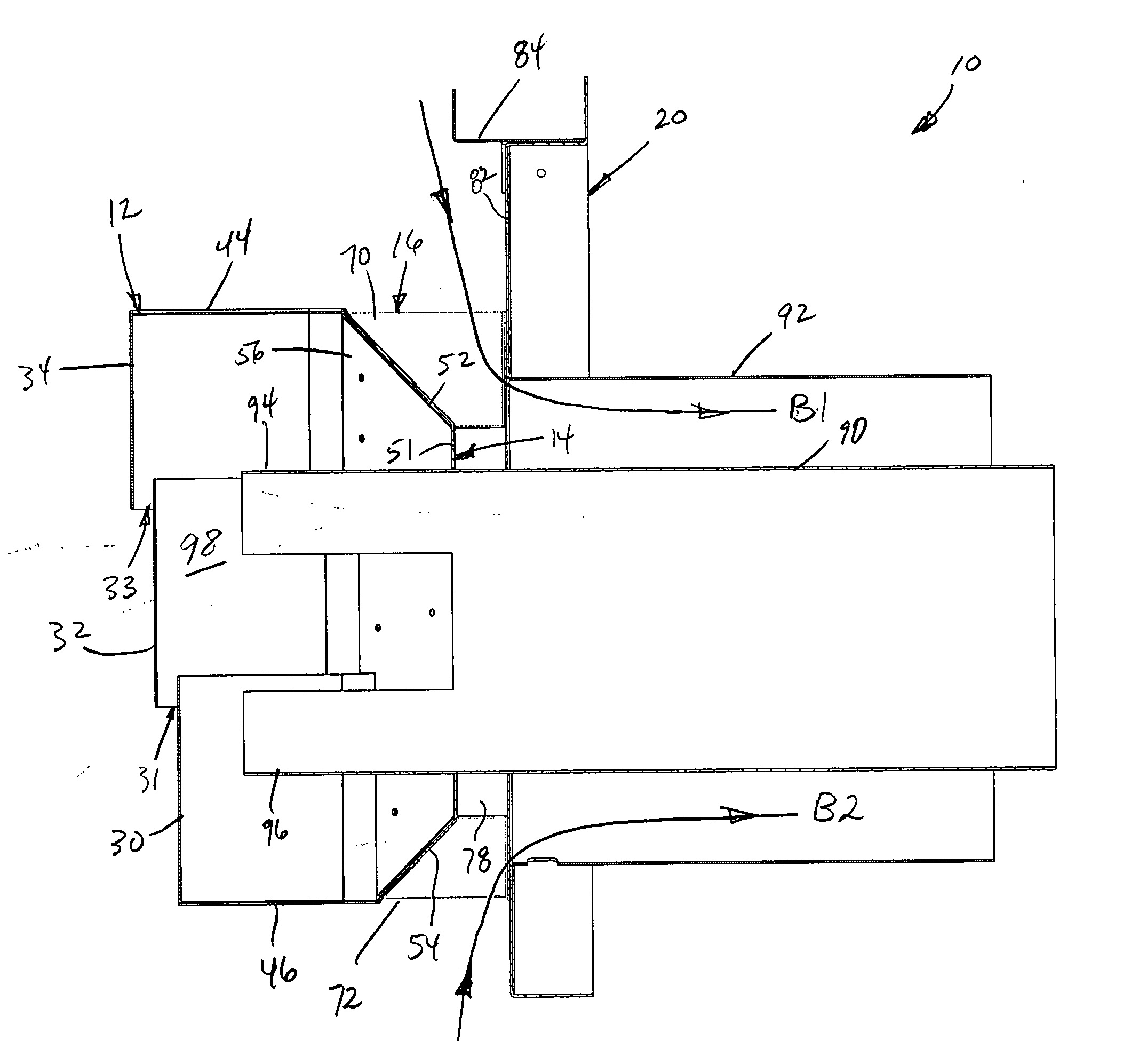
[0021] The present invention generally relates to vents, vent covers, vent caps, and vent assemblies. Example embodiments described herein are directed to vent systems and structures that integrate features into a single configuration. The example systems include an exhaust member configured to deliver exhaust fluids, and an intake member configured to receive intake fluids. The exhaust and intake members are preferably coaxially oriented with the exhaust member extending within the intake member. This coaxial arrangement (sometimes referred to as a B-vent arrangement) may be well suited for cooling the exhaust gases in the exhaust member with the intake fluids flowing through the intake member. Other embodiments have included other arrangements of the exhaust and intake members relative to each other.

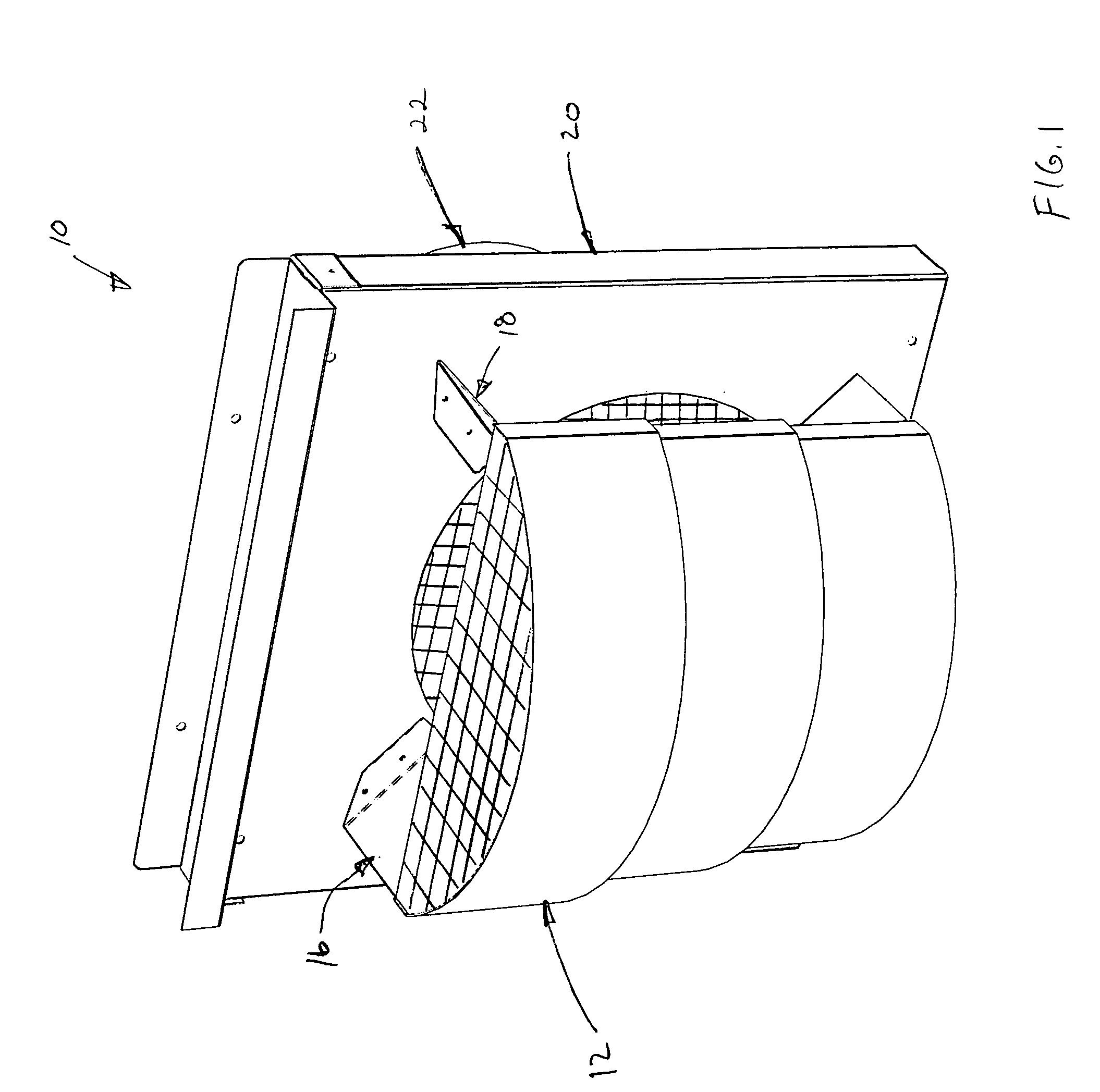
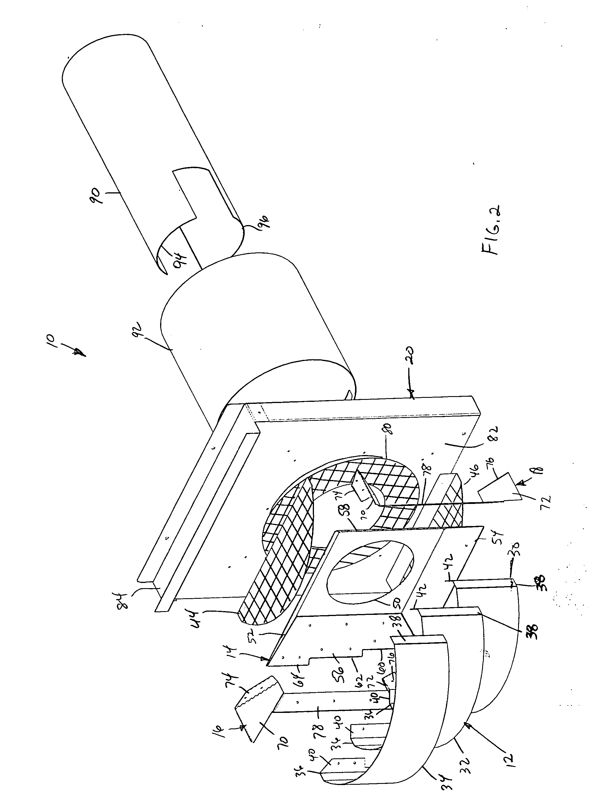
[0022] An example vent assembly 10 that illustrates principles of the present invention is shown in FIGS. 1-5. Venting system 10 includes a vent cover assembly 12, a divider 14, first...


PUM


Abstract

A vent assembly for use with a vent pipe assembly that includes an intake member defining an intake aperture and an exhaust member defining an exhaust aperture. The vent assembly may include a flow guide positioned adjacent to the intake aperture and configured to direct fluid flow into the intake aperture, a divider positioned between the exhaust aperture and the intake aperture and configured to minimize fluid flow between the exhaust aperture and the intake aperture, and a wind shield coupled to a distal end of the exhaust member adjacent to the exhaust aperture and configured to minimize reverse flow into the exhaust aperture. The vent assembly is configured to minimize the flow of fluids exhausted from the exhaust aperture into the intake aperture, to minimize reverse flow in the exhaust member, and to improve the flow of intake air into the intake aperture.

Description

BACKGROUND OF THE INVENTION [0001] 1. Field of the Invention [0002] The present invention generally relates to components of a vent system for a heating appliance, and more particularly relates to a vent structure that provides vent cap and vent cover functionality and is suited for use with a vent system with an exhaust vent opening and intake vent opening. [0003] 2. Related Art [0004] Exterior intake and / or exhaust venting systems are generally known for use in buildings and other such structures. Such vents can be used for a variety of venting purposes, for example, to vent fireplaces, furnaces, water heaters, boilers, dryers, exhaust fans, and a many other such appliances and devices. Some such vents are primarily exhaust vents while others are primarily intake vents, and still others include structure that allows them to function as both intake and exhaust vents. [0005] In one example, chimneyless gas fireplaces often include intake / exhaust venting units that are mounted on the...

Claims


Application Information

Patent Timeline
IPC IPC(8): F23L17/04
CPCF23L17/14
Inventor ZHOU, YINGYINGSHIN, DOSUNERICKSON, BRIAN
Owner HNI TECH INC
Why Eureka
Try Eureka