Method and process for cleaning pipes and components in a piped medical vacuum system

Active Publication Date: 2013-01-10
LISEC SCOTT E
View PDF2 Cites 0 Cited by
  • Summary
  • Abstract
  • Description
  • Claims
  • Application Information

AI Technical Summary

Benefits of technology

The patent describes a way to increase the flow of a clinical vacuum system by using an enzymatic solution. This solution is introduced into the system and then removed after exposure to the piping. The technical effect is an improved ability to maintain flow in the system, even when there is no inlet flow.

Problems solved by technology

The efficiency of a clinical vacuum suction system can be compromised where lint, debris or dried body fluids accumulate over time and work to reduce vacuum system performance.
When aspiration becomes slow and difficult, it is imperative that the vacuum system be cleaned.
Reduced efficiencies can also result in the failure of the clinical vacuum suction system to comply with certain mandatory regulatory requirements.

Method used


Image

  • Method and process for cleaning pipes and components in a piped medical vacuum system

Examples


Embodiment Construction

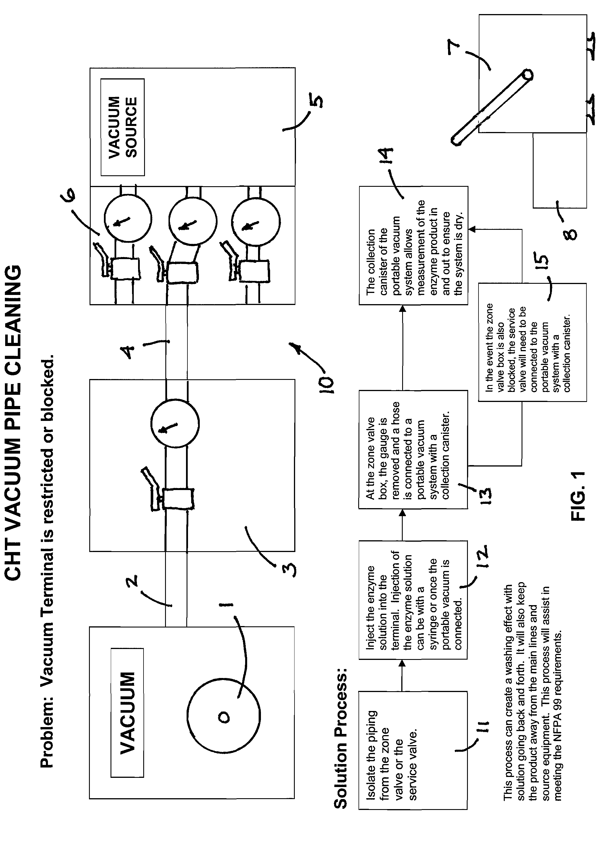
[0008]Referring now to FIG. 1, it illustrates the essential steps of the method and process of the present invention. It is assumed for purposes of this disclosure that the clinical vacuum system, generally identified 10, with which the method and process can be used comprises several essential components. One component is the vacuum terminal 1, which is that portion of the system 10 at which the user can access the system 10 from within the surgical suite or the medical procedure room. Another component is the piping 2, 4 leading from the vacuum terminal 1 to a vacuum source 5, which is typically a vacuum pump. At some point between the vacuum terminal 1 and pump 5 is a service valve 6, which controls access to the vacuum source 5, and a zone valve box 3, which provides gauging for measuring the vacuum extraction rate that is available in the piping 2, 4 during normal operation and provides a secondary control for access to the vacuum source 5. That is, both the service valve 6 and...


PUM


Abstract

A method and process is provided to help increase flow within the piping of a clinical vacuum system under low flow inlet conditions and to re-establish flow under zero flow inlet conditions, among other things. The method and process broadly uses the steps of isolating and accessing the piping of the clinical vacuum system, introducing an enzymatic solution to the piping, and then extracting the solution following exposure of the solution to the piping to remove complex organic materials from the piping. A portable collection canister can be used to measure the amount of enzymatic solution that is put into the piping and removed from the piping to ensure that the system is dry. The collection canister can be connected via hose to a zone valve box of the system or to a service valve of the system.

Description

[0001]This application claims the benefit of U.S. Provisional Application No. 61 / 430,001, filed Jan. 5, 2011.FIELD OF THE INVENTION[0002]This invention relates generally to piped medical gas systems, including piped medical vacuum systems, of the clinical type that are installed and used in medical facilities. More specifically, it relates to a method and process for cleaning the pipes and other components that are used in such a piped medical vacuum system for the purpose of removing fluid and tissue debris from vacuum system pipes and maintaining or re-establishing the efficiency of performance of the vacuum system.BACKGROUND OF THE INVENTION[0003]Medical facilities are typically provided with a centrally piped system for accessing medical gases and for providing clinical vacuum suction. Clinical suction, or aspiration, represents an absolutely necessary tool in all surgical procedures and must be readily available and fully functional in all surgical and procedure suites, as well...

Claims


Application Information

Patent Timeline
IPC IPC(8): C11D3/386C12S9/00
CPCB08B9/027A61M1/0066C11D11/0041C11D3/386A61M1/80C11D2111/20
Inventor LISEC, SCOTT E.
Owner LISEC SCOTT E
Why Eureka
Try Eureka