
Vtol aerial vehicle

a technology of vertical landing and aerial vehicles, which is applied in vertical landing/take-off aircrafts, airflow influencers, aircraft navigation control, etc., can solve the problems of inability to hover over a fixed spatial point, inability to optimize fixed wing uavs for delivering logistics supplies, ordinances or payloads to designated targets, and may not operate effectively in confined air space. achieve the effect of increasing the range of aircra

Active Publication Date: 2010-09-09
FRONTLINE AEROSPACE
View PDF47 Cites 63 Cited by
  • Summary
  • Abstract
  • Description
  • Claims
  • Application Information

AI Technical Summary

Benefits of technology

[0008]One object of the present invention is to provide a VTOL aircraft, which may be a UAV aircraft, that is capable of vertical takeoff and landing, is capable of traveling of slow speeds including hover. It also permits high speed horizontal flight (i.e., forward flight) to allow for increased range of the aircraft.
[0010]When each set of wings is interconnected to the fuselage at points forward and aft of the vertical reference axis defined by the lift fan, the center of gravity may be disposed between these forward and aft connections to improve stability of the aircraft. In one particular embodiment, the center of gravity of the aircraft is located coincidentally with the rotational axis of the lift fan.
[0014]In one arrangement, where the wing sets utilize an end plate, such an end plate may be utilized to mount additional components to the aircraft. In one particular arrangement, additional air foils may be mounted to the end plates. Such air foils may be selectively deployable to provide additional lift that may allow, for example, reduced forward flying speeds for the aircraft. Likewise, such air foils may be retracted to allow reduced drag during high speed forward flight.

Problems solved by technology

A further difficulty with fixed wing UAV configurations is that such UAVs may not operate effectively in confined air space.
That is, as fixed wing UAVs require forward motion to maintain lift, they are not capable of hovering over a fixed spatial point.
Accordingly, such fixed wing UAVs are not optimized at delivering logistics supplies, ordinances or payloads to designated targets.
However, such helicopter UAV configurations often have relatively slow forward speeds as the rotating blades create a large aerodynamic drag.
In this regard, both the speed and the range of helicopter UAV configurations can be limited.
Such ducted type UAVs often suffer from stability issues as well as limited speed in forward flight.
In particular, the ducted rotors cannot be oriented such that the plane of rotors is perpendicular to the direction of travel of the aircraft.

Method used


Image

  • Vtol aerial vehicle
  • Vtol aerial vehicle
  • Vtol aerial vehicle

Examples


Embodiment Construction

[0025]Reference will now be made to the drawings wherein like numerals refer to like parts throughout. Though discussed herein primarily in reference to unmanned aerial vehicles (UAVs), it will be expressly understood that various aspects of the disclosure have broader application. In particular, various aspects of the disclosed aerial vehicle are applicable to manned aerial vehicles. Therefore, the proceeding disclosure is provided by way of example and not by way of limitation.

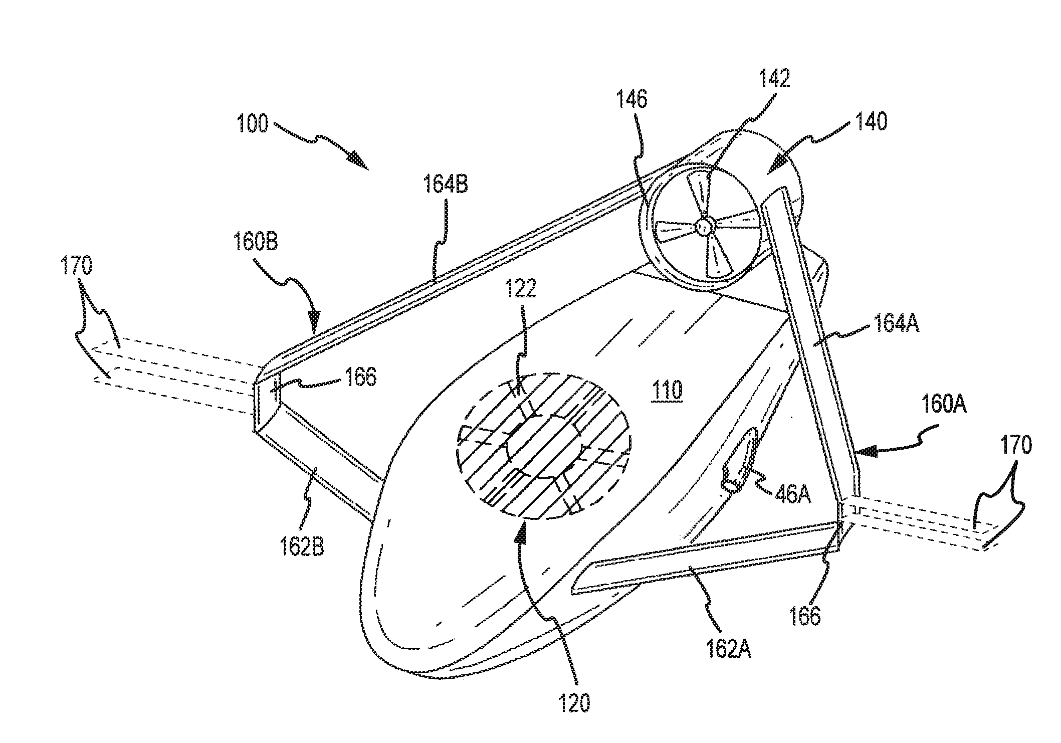
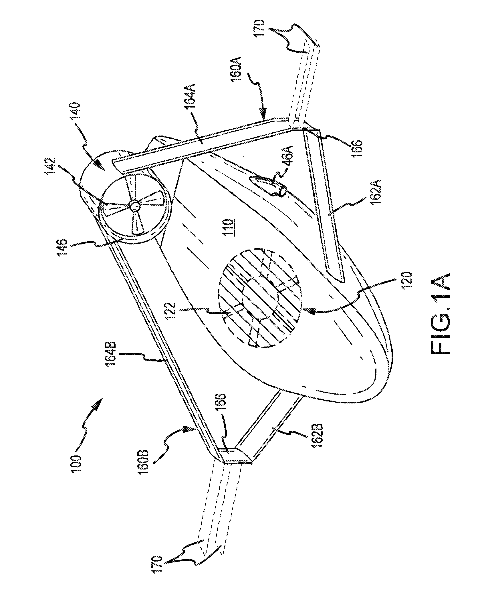
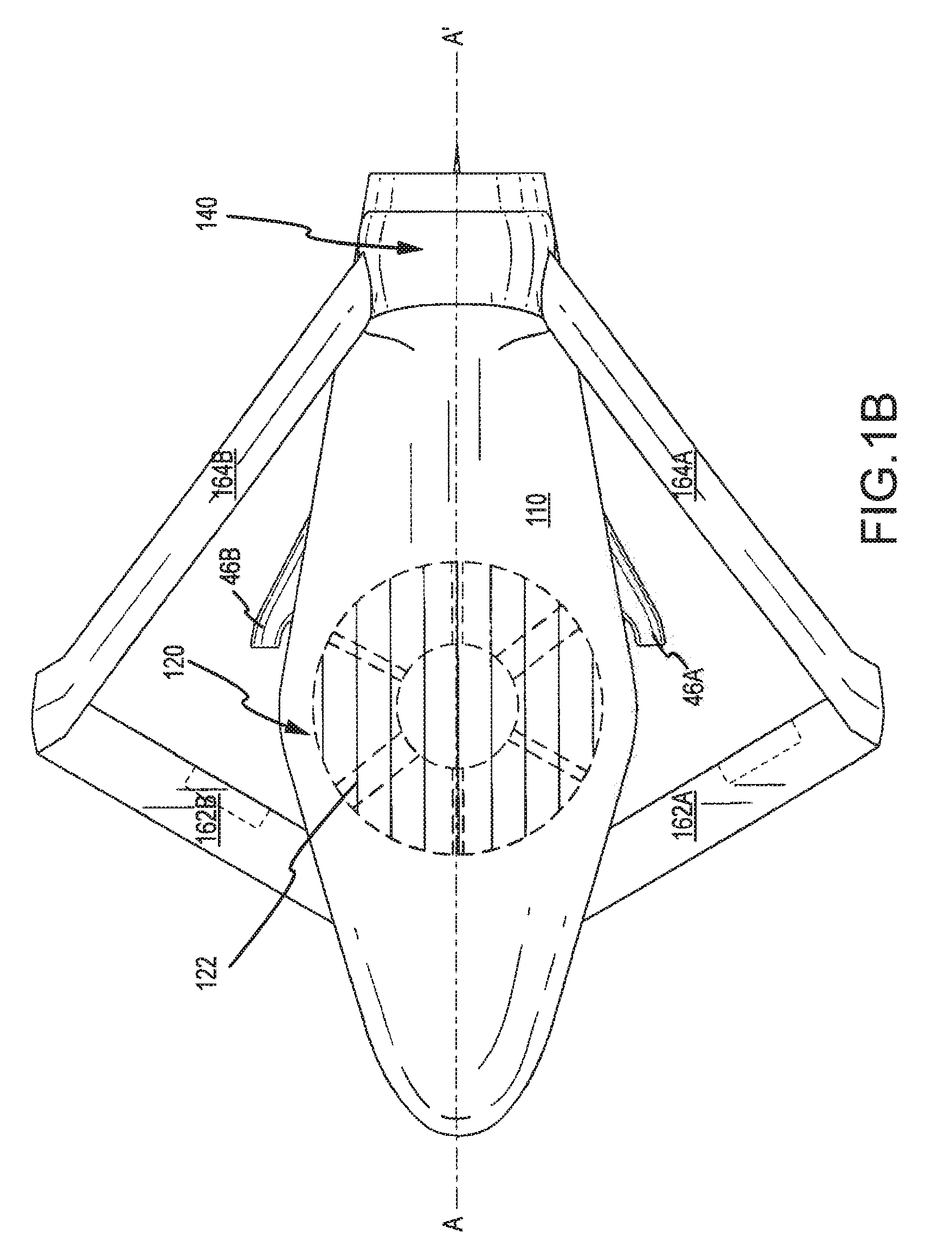
[0026]FIGS. 1A and 1B illustrates perspective and top views of one embodiment of an unmanned aerial vehicle (UAV) or aircraft 100 in accordance with one aspect of the present invention. The aircraft 100 includes a fuselage 110 that houses a ducted fan assembly 120. The ducted fan assembly is defined by a dual rotor assembly 122 that is mounted within a duct 118 that extends substantially vertically through the fuselage 110. Generally, the rotor assembly 122 is fixedly connected within the fuselage in axial a...


PUM


Abstract

A vertical take off and landing (VTOL) aircraft, which may be a UAV aircraft, is disclosed. The VTOL is capable of vertical takeoff and landing, hovering and traveling of slow speeds. In addition the VTOL permits high-speed forward flight that allows for increasing the range of the aircraft.

Description

CROSS-REFERENCE TO RELATED APPLICATION[0001]This application claims priority and the benefit of the filing date under 35 U.S.C. 119 to U.S. Provisional Application No. 61 / 059,627, entitled, “VTOL Aerial Vehicle,” filed on Jun. 6, 2008, the contents of which are incorporated herein as if set forth in full.FIELD OF INVENTION[0002]The present invention relates to vertical takeoff and landing (VTOL) aerial vehicles. In particular, the application is directed towards a high-speed VTOL vehicle having extended range and payload capabilities. One embodiment is a VTOL unmanned aerial vehicle (UAV).BACKGROUND OF THE INVENTION[0003]Use of unmanned aerial vehicles (UAVs) has become increasingly common with the advent of automated flight based on GPS as well as real-time communications that allow for remote UAV operation. For example, UAVs are commonly used by the military to provide surveillance, reconnaissance, target acquisition, communications relay, casualty evacuation, ordinance delivery a...

Claims


Application Information

Patent Timeline
IPC IPC(8): B64C29/00B64C15/00
CPCB64C29/0025B64C39/024B64C2201/162B64C2201/021B64C2201/088B64C39/068B64U10/25B64U70/80B64U50/14B64U60/40B64U30/26B64U20/65B64U50/20B64U50/12B64U30/10B64U30/24
Inventor WOOD, RYAN S.CUMMINGS, DAROLD B.HALL, DAVID W.
Owner FRONTLINE AEROSPACE
Learn More