

Touch panel
a technology of touch panel and touch screen, applied in the field of touch panel, can solve problems such as difficult to collect high-resolution color data
- Summary
- Abstract
- Description
- Claims
- Application Information
AI Technical Summary
Benefits of technology
Problems solved by technology
Method used
Image

Examples
embodiment 1
[0026]In this embodiment, a touch panel will be described with reference to FIGS. 1 to 7.
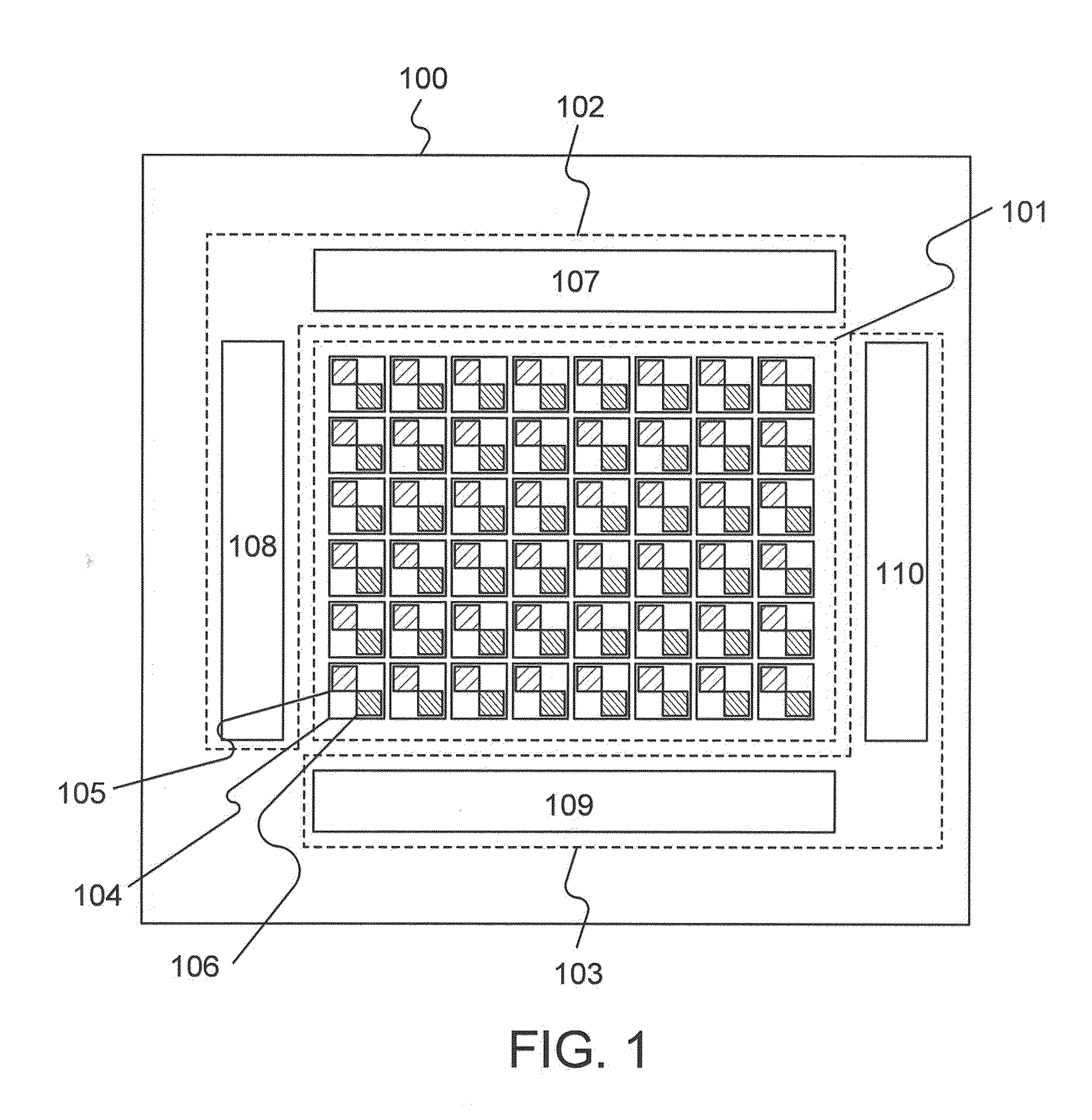
[0027]The structure of the touch panel will be described with reference to FIG. 1. A touch panel 100 includes a pixel portion 101, a display element control circuit 102, and a photosensor control circuit 103.
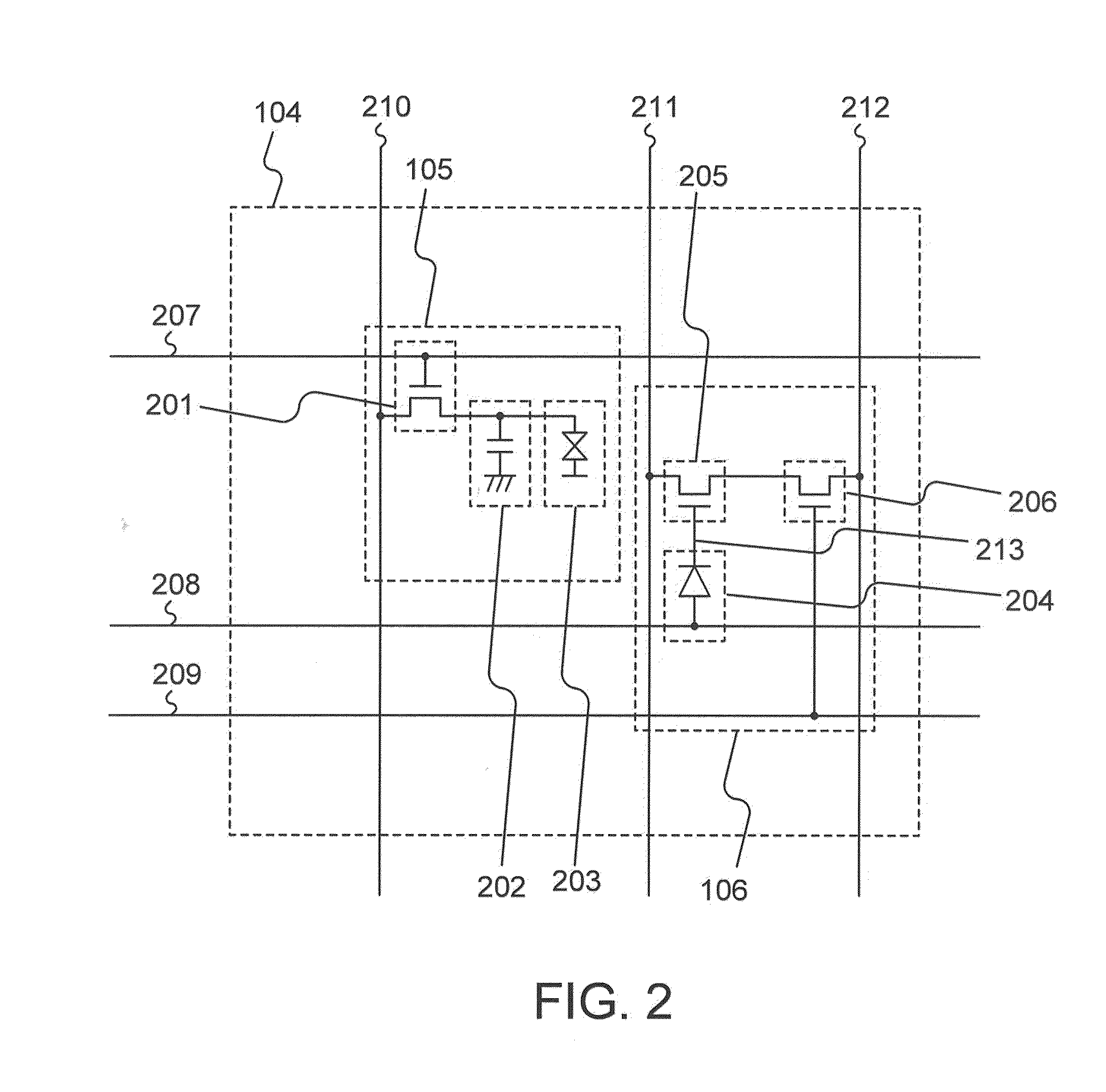
[0028]The pixel portion 101 includes a plurality of pixels 104. The pixels 104 each include a display element portion 105 and a photosensor portion 106. The plurality of pixels 104 are arranged in matrix. For example, the pixels 104 which detect light with a first color are provided in an n-th column (n is a natural number), the pixels 104 which detect light with a second color are provided in an (n+1)th column, and the pixels 104 which detect light with a third color are provided in an (n+2)th column. The first color, the second color, and the third color represent, for example, R (red), G (green), and B (blue). In addition, a red color filter is provided so as to overlap with the pixels 10...
embodiment 2
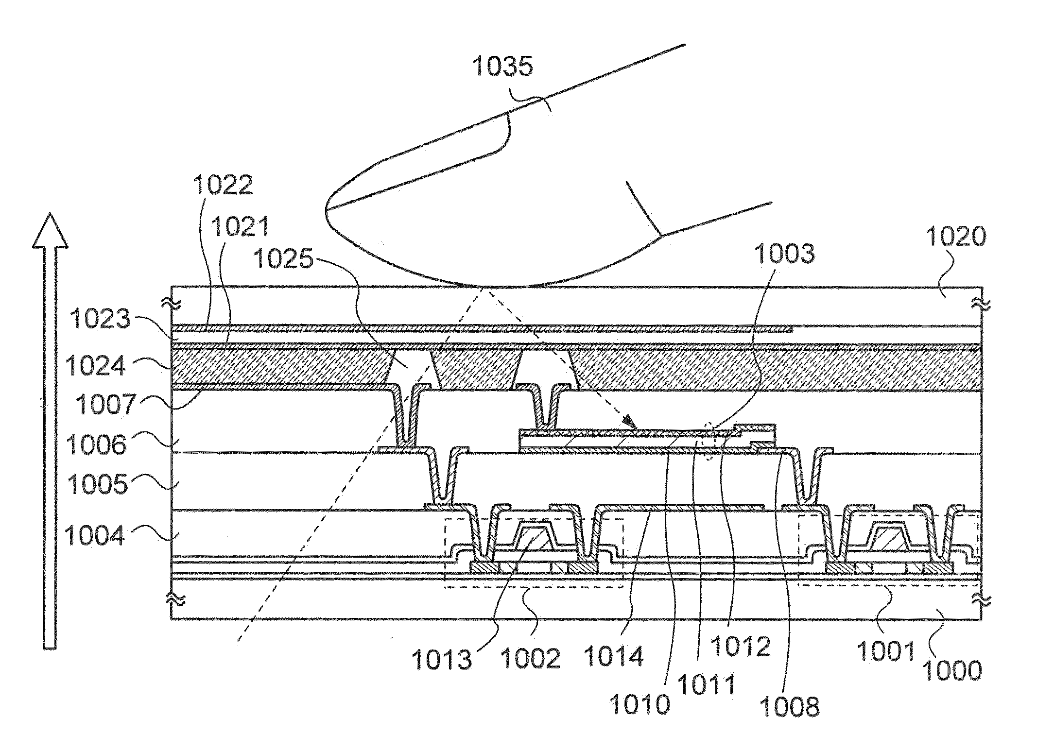
[0076]In this embodiment, the touch panel described in Embodiment 1 will be described with reference to FIGS. 8 and 9. In this embodiment, the touch panel includes a photosensor and a display element. The display element includes a liquid crystal element or a light emitting element.
[0077]FIG. 8 illustrates, as for the touch panel described in Embodiment 1, an example of the cross-sectional view of a liquid crystal display device in which a display element includes a liquid crystal element. A situation is illustrated where light from a backlight reflects off a finger 1035, which is an object to be detected, and is shone on a photosensor 1003.
[0078]As a substrate 1000, a light-transmitting substrate such as a glass substrate or a quartz substrate is used. Over the substrate 1000, a thin film transistor 1001, a thin film transistor 1002, and a photosensor 1003 are provided. The photosensor 1003 is formed by stacking an n-type semiconductor layer 1010, an i-type semiconductor layer 1011...
embodiment 3
[0107]In this embodiment, an example of an electronic device using a touch panel will be described with reference to FIGS. 10A to 10F.
[0108]A mobile phone shown in FIG. 10A includes a display portion 9101. A portable information terminal shown in FIG. 10B includes a display portion 9201, an input pen 9202, and the like. A digital video camera shown in FIG. 10C includes a display portion 9301, a display portion 9302, and the like. A portable game machine shown in FIG. 10D includes a display portion 9401 and the like. A portable information terminal shown in FIG. 10E includes a display portion 9501 and the like. A television device shown in FIG. 10F includes a display portion 9601, an input pen 9602, and the like. The touch panel which is an embodiment of the present invention can be used for the electronic devices shown in FIGS. 10A to 10F. With the use of the touch panel which is an embodiment of the present invention, a touch panel that enables data sensing with multi-gray scale ca...
PUM
 Abstract
Description
Claims
Application Information