Multi-Input Multi-Output Time Encoding And Decoding Machines

a multi-output, time-encoding technology, applied in the direction of amplitude demodulation, code conversion, television system, etc., can solve the problem that the traditional synchronous sampling of the amplitude of a signal becomes more difficul

Inactive Publication Date: 2010-09-09
THE TRUSTEES OF COLUMBIA UNIV IN THE CITY OF NEW YORK
View PDF16 Cites 94 Cited by
  • Summary
  • Abstract
  • Description
  • Claims
  • Application Information

AI Technical Summary

Problems solved by technology

While digital signals can be processed at the lower supply voltages, traditional synchronous sampling of the amplitude of a signal becomes more difficult as the available power supply voltage is reduced and each bit in the A / D or D / A converter reflects a substantially lower voltage increment.

Method used


Image

  • Multi-Input Multi-Output Time Encoding And Decoding Machines
  • Multi-Input Multi-Output Time Encoding And Decoding Machines
  • Multi-Input Multi-Output Time Encoding And Decoding Machines

Examples


Embodiment Construction

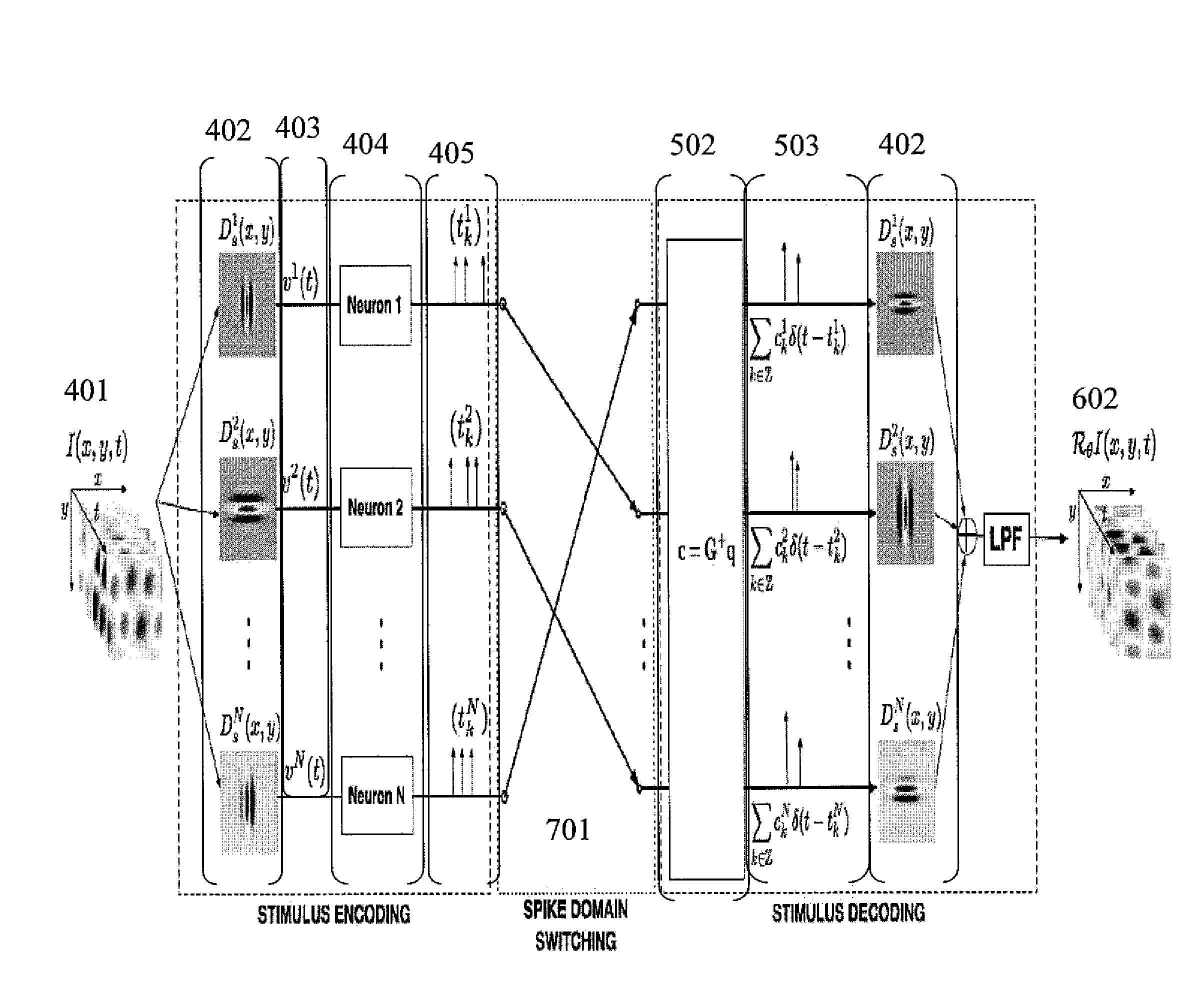
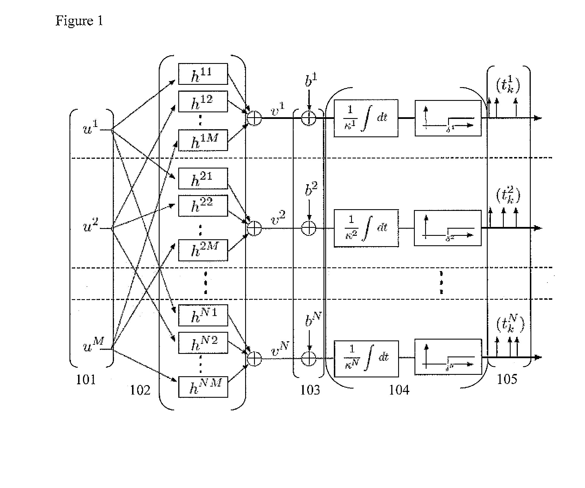
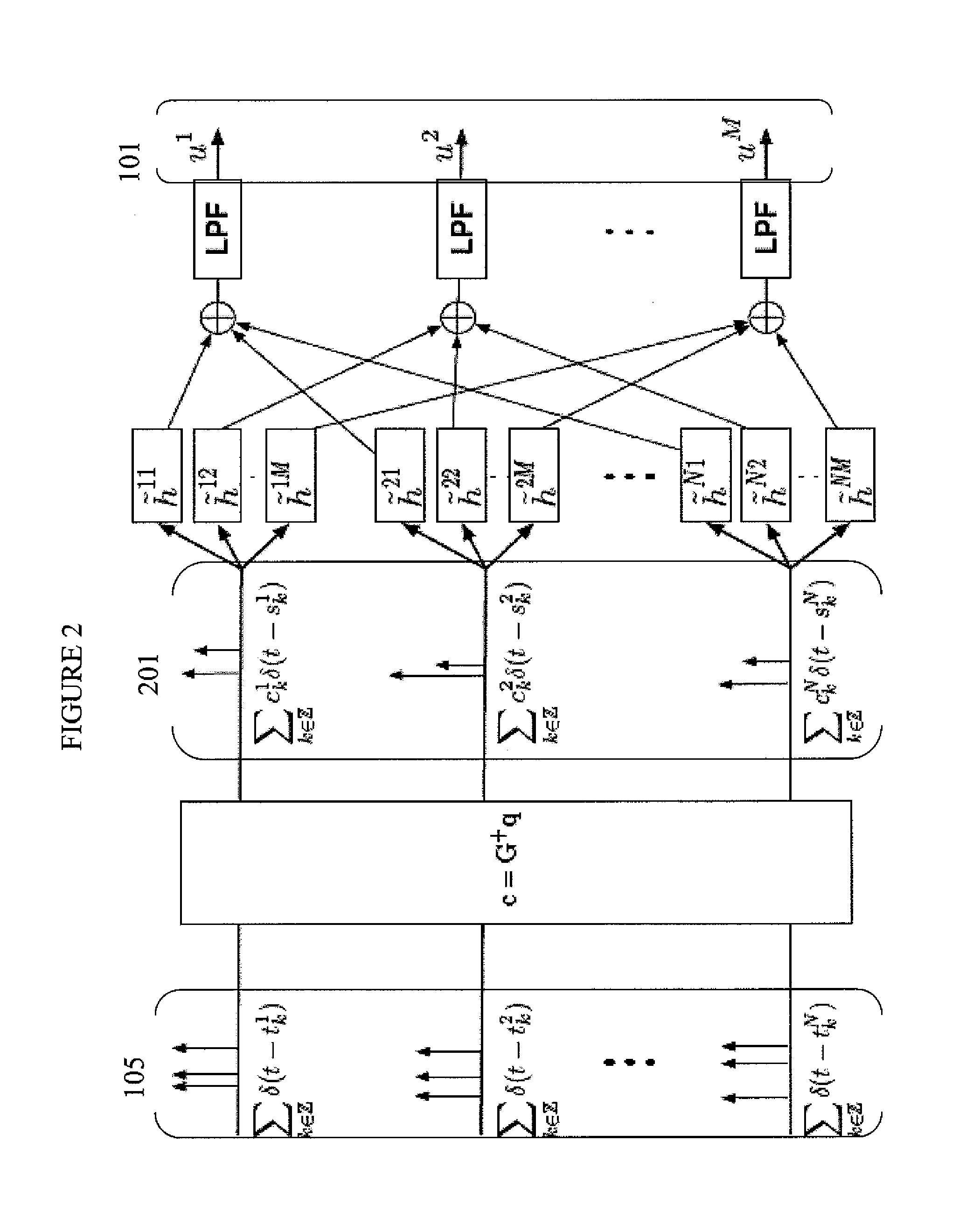
[0039]Improved systems, methods, and applications of Time Encoding and Decoding machines are disclose herein.

[0040]Asynchronous Sigma / Delta modulators as well as FM modulators can encode information in the time domain as described in “Perfect Recovery and Sensitivity Analysis of Time Encoded Bandlimited Signals” by A. A. Lazar and L. T. Toth (IEEE Transactions on Circuits and Systems-I: Regular Papers, 51(10):2060-2073, October 2004), which is incorporated by reference. More general TEMs with multiplicative coupling, feedforward and feedback have also been characterized by A. A. Lazar in “Time Encoding Machines with Multiplicative Coupling, Feedback and Feedforward” (IEEE Transactions on Circuits and Systems II: Express Briefs, 53(8):672-676, August 2006), which is incorporated by reference. TEMs realized as single and as a population of integrate-and-fire neurons are described by A. A. Lazar in “Multichannel Time Encoding with Integrate-and-Fire Neurons” (Neurocomputing, 65-66:401-...


PUM


Abstract

Methods and systems for encoding and decoding signals using a Multi-input Multi-output Time Encoding Machine (TEM) and Time Decoding Machine are disclosed herein.

Description

CROSS REFERENCE TO RELATED APPLICATIONS[0001]This application is a continuation of International Application PCT / US2008 / 068790 filed Jun. 30, 2008, which claims priority from: U.S. patent application Ser. No. 11 / 965,337 filed on Dec. 27, 2007; U.S. Provisional Patent Application No. 60 / 946,918 filed on Jun. 28, 2007; and U.S. Provisional Patent Application No. 61 / 037,224 filed on Mar. 17, 2008, the entire disclosures of which are explicitly incorporated by reference herein.STATEMENT REGARDING FEDERALLY SPONSORED RESEARCH[0002]This invention was made with government support under grants CCF-06-35252, awarded by the National Science Foundation, and R01 DC008701-01, awarded by the National Institutes of Health. The government has certain rights in the invention.BACKGROUND[0003]1. Field[0004]The present application relates to methods and systems for a Multi-input Multi-output (MIMO) Time Encoding Machines (TEMs) and Time Decoding Machines (TDMs) as well as uses of TEMs and TDMs for enco...

Claims


Application Information

Patent Timeline
Patent Type & Authority Applications(United States)
IPC IPC(8): H04L27/00H04N5/38H04N5/44
CPCH03M3/466H03M1/1205H03M1/125H03M3/504H03M1/662H03M1/82H03M3/43H03M1/50G06N3/049
Inventor LAZAR, AUREL A.PNEVMATIKAKIS, EFTYCHIOS A.
Owner THE TRUSTEES OF COLUMBIA UNIV IN THE CITY OF NEW YORK
Why Eureka
Try Eureka