Vigilante acoustic detection, location and response system

Inactive Publication Date: 2010-09-09
KORDIS THOMAS F +1
View PDF21 Cites 78 Cited by
  • Summary
  • Abstract
  • Description
  • Claims
  • Application Information

AI Technical Summary

Problems solved by technology

By bouncing the laser off of the bulletfrom multiple locations, the bullet's location in space may becalculated (with limited accuracy).
Since the shock wave is continuously generated as the bullet moves through space, it is computationally very intensive to reconstruct the projectile's path.
Disadvantages:This system does not determine the origin of the sound.
It can be appreciated that small errors in the measurement of the successive positions can result in a very large error in the calculated trajectory.The calculated trajectory of the bullet does not determine the bullet's origin.
For this reason, shockwave systems are frequently combined with other systems to assist in determining the actual origin of the bullet.This system can be defeated by using a silencer on the rifle, since silencers drop the speed of even high velocity bullets below Mach 1.Supersonic bullets will no longer be detected if they drop below Mach 1 during flight.It is expensive.It is not very portable.
Most systems are vehicle mounted.It uses considerable amounts of power, and is not well suited to battery operation.It requires timing accuracies on the order of microseconds or better to achieve reasonable accuracy.
The system is not inherently omnidirectional, and currently available systems have only 120° fields of view, leaving ⅔ of the surrounding unmonitored and therefore undefended.This system only provides relative bearing and azimuth information.
This can be supplemented with a laser range-finder, but this adds complexity to the overall system.This system can be spoofed by glints and reflections.This system is generally bulky, complex, power consuming and expensive.
The active laser detection system is a complex, expensive and rather desperate method of protecting limited volumes of space for limited amounts of time.
Disadvantages:This system must flood a suspected volume of space with an extremely high speed, raster scanning laser.This system and operator must have some knowledge of likely sources of sniper fire in order to protect the correct space.Multiple detectors must surround the protected space.The probability of obtaining a sufficient number of reflections off of a bullet to allow the calculation of a trajectory is very low in typical combat conditions.This system suffers the same accuracy problems that all trigonometric and triangulation systems suffer.This system is not amenable for use in mobile applications.This system is bulky, expensive, and draws large amounts of power.
Some of the trajectory calculating systems are subject to large errors in the point of origin due to relatively small errors in the calculation of the bullet's successive position in space.
DisadvantagesThese systems are bulky, expensive and power drains.These systems suffer mobility and power limitations worse than its least mobile and most power hungry component.Competitive manufacturers must cooperate to cross-license technology.Complexity is the enemy of reliability.
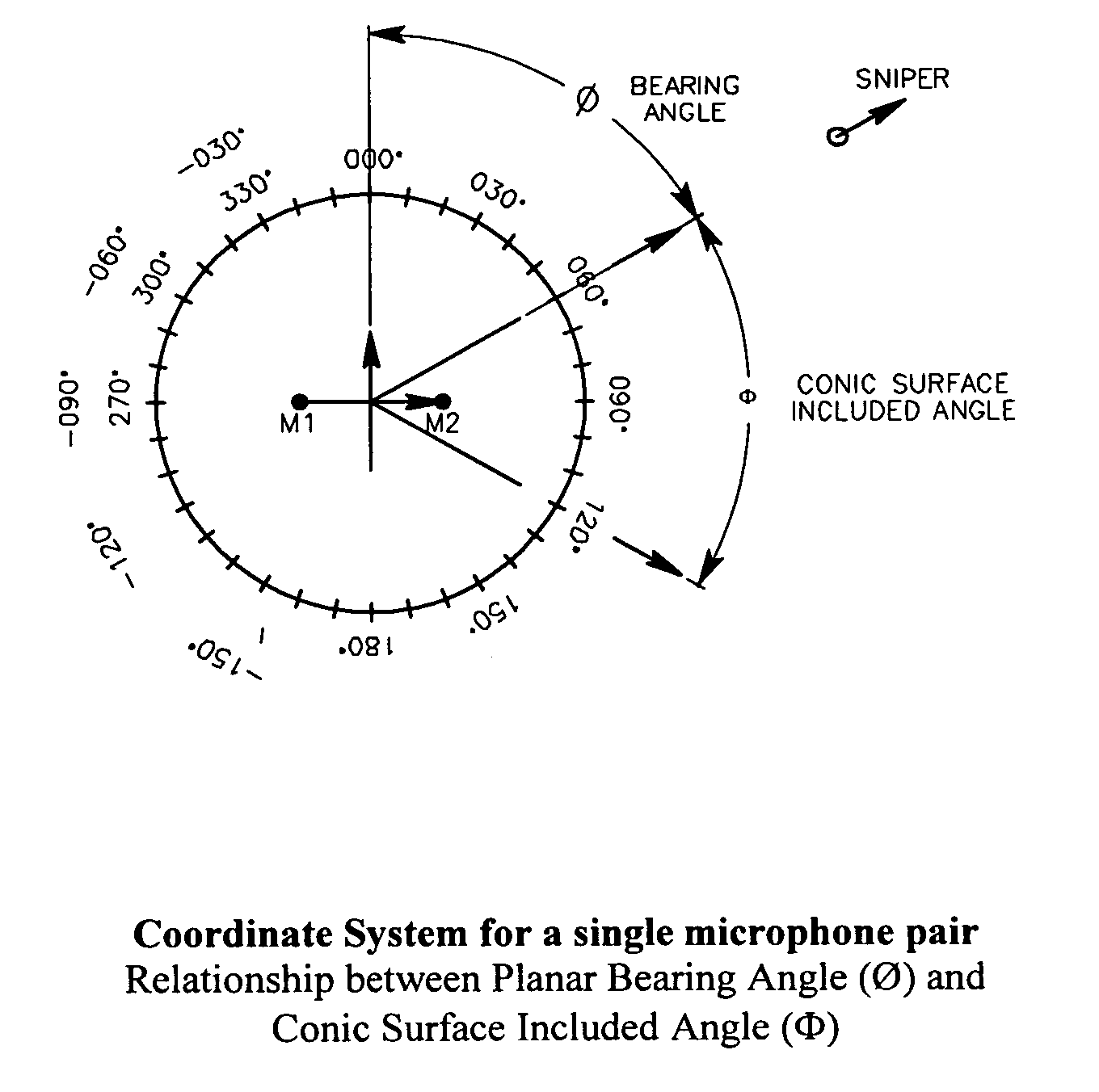
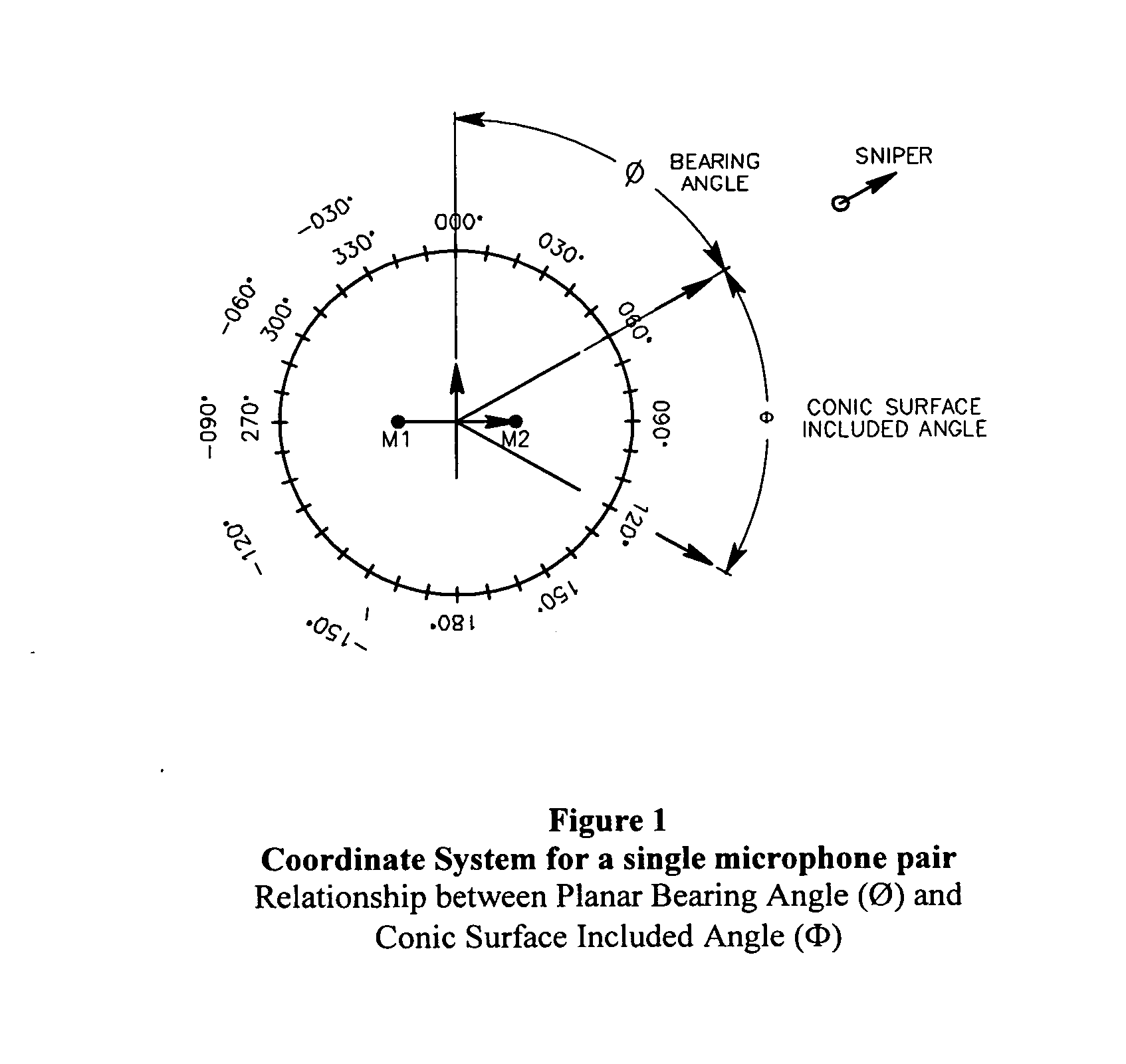
It is easy to see that, if the bearing angle is greater than 70°, any effect that introduces small errors into the timing signals (such as ambient winds) will also introduce large errors into the calculated bearing angle.
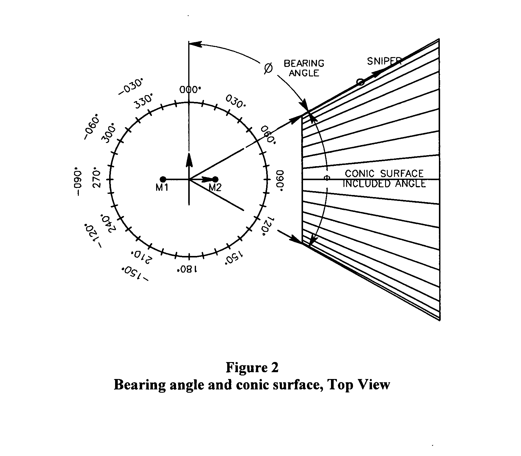
It is evident that even small bearing errors can result in large positional errors when they are projected out long distances.
Table 3 below demonstrates how relatively modest bearing errors result in large positional errors when they are projected out long distances.
The significant consequence of this analysis is that slight errors in the calculated bearing angle result in large positional errors when 1) the bearing angles are in the imprecise zones between 70°<Ø<90° and 2) those bearing errors are projected out the long distances that typically separate a sniper from a sniper detector.
However the problem of the errors associated with high bearing angles (Ø>70°) does not go away with crossed pairs of microphones.
In fact, the problem is made worse.

Method used


Image

  • Vigilante acoustic detection, location and response system
  • Vigilante acoustic detection, location and response system
  • Vigilante acoustic detection, location and response system

Examples


Embodiment Construction

[0128]Vigilante comes in four configurations:[0129]The Personal Defense System is designed to protect small numbers of foot soldiers when on maneuvers or encamped in potentially hostile territory.[0130]The Convoy Defense System is designed to protect convoys or motorcades.[0131]The Fixed Base Defense System is designed to protect outposts, buildings, embassies, depots or other large fixed bases of operation.[0132]The Remotely Piloted Vehicle Defense System is designed to incorporate its sensors into small RPVs that will circle the protected asset under radio control of the central processor.

[0133]The component systems of each configuration are similar:[0134]remote sensors with GPS location capability and a radio data link to the central processor[0135]a central processor running the custom Vigilante software program, data linked to the remote sensors and to the response subsystem.[0136]the response subsystem, which is available in either lethal (e.g., computer targeted mortar batter...


PUM


Abstract

A system and method for detecting the exact location of an acoustic event, the system comprising a plurality of variably spaced sensors, wherein each sensor comprises an omnidirectional microphone for detecting the acoustic event; a global positioning system (GPS); and a transmitter receiver for transmitting (i) the time that the acoustic event arrived at a particular sensor and (ii) the location of the particular sensor at the time the acoustic event arrived at the particular sensor; and a central processor radio-linked to the plurality of variably spaced sensors comprising a software program comprising at least one algorithm for determining the location of the acoustic event.

Description

REFERENCE TO PENDING PRIOR PATENT APPLICATION[0001]This patent application claims benefit of pending prior U.S. Provisional Patent Application Ser. No. 60 / 749,741, filed Dec. 13, 2005 by Thomas Kordis et al. for VIGILANTE ACOUSTIC DETECTION, LOCATION AND RESPONSE SYSTEM (Attorney's Docket No. KORDIS-5 PROV).FIELD OF THE INVENTION[0002]This disclosure describes a new acoustic system suitable for the rapid, accurate detection and location of a sudden acoustic event such as a gunshot from a sniper or an explosion. This system falls into the category of a muzzle blast detection system as described in the next section. However new and unique features have been incorporated into both the hardware and software of this system that provide several significant improvements over competitive systems.[0003]The unique features of this system include:[0004]The ability to calculate the location of a sniper or acoustic event rapidly (i.e., in approximately one second).[0005]An order of magnitude imp...

Claims


Application Information

Patent Timeline
Patent Type & Authority Applications(United States)
IPC IPC(8): G01S3/80
CPCG01S5/0027G01S5/0036G01S5/22G01S5/0252G01S5/0221
Inventor KORDIS, THOMAS F.MCCLAIN, FRED
Owner KORDIS THOMAS F
Why Eureka
Try Eureka