
System for evacuating the residual heat from a liquid metal or molten salts cooled nuclear reactor

a liquid metal or molten salts cooled, nuclear reactor technology, applied in the direction of tubular elements, lighting and heating apparatus, tubular conduit assemblies, etc., can solve the problems of difficult water use, high cost, and insufficient reliability according to known solutions, so as to reduce the drawbacks of water use.

Inactive Publication Date: 2010-09-09
DEL NOVA VIS +1
View PDF3 Cites 5 Cited by
  • Summary
  • Abstract
  • Description
  • Claims
  • Application Information

AI Technical Summary

Benefits of technology

"The present invention is a system designed to improve the evacuation of residual heat from a nuclear reactor. The goal is to eliminate or reduce the drawbacks of current solutions. The system is specifically designed for liquid metal or molten salts cooled nuclear reactors."

Problems solved by technology

In nuclear reactors that use water as primary cooling fluid, it is natural to use water also for the residual heat evacuation circuit, whilst for reactors that use primary cooling fluids other than water, in particular liquid metals or molten salts, the use of water is rendered problematical on account of the incompatibility between the two fluids, as in the case of sodium-cooled reactors, or of the risk of solidification of the primary fluid, as in general occurs in reactors cooled with liquid metal or molten salts.
Consequently, auxiliary circuits operating with liquid metals or molten salts are used, which are, however, according to the known solutions, very costly and not fully satisfactory in terms of reliability.

Method used


Image

  • System for evacuating the residual heat from a liquid metal or molten salts cooled nuclear reactor
  • System for evacuating the residual heat from a liquid metal or molten salts cooled nuclear reactor
  • System for evacuating the residual heat from a liquid metal or molten salts cooled nuclear reactor

Examples


Embodiment Construction

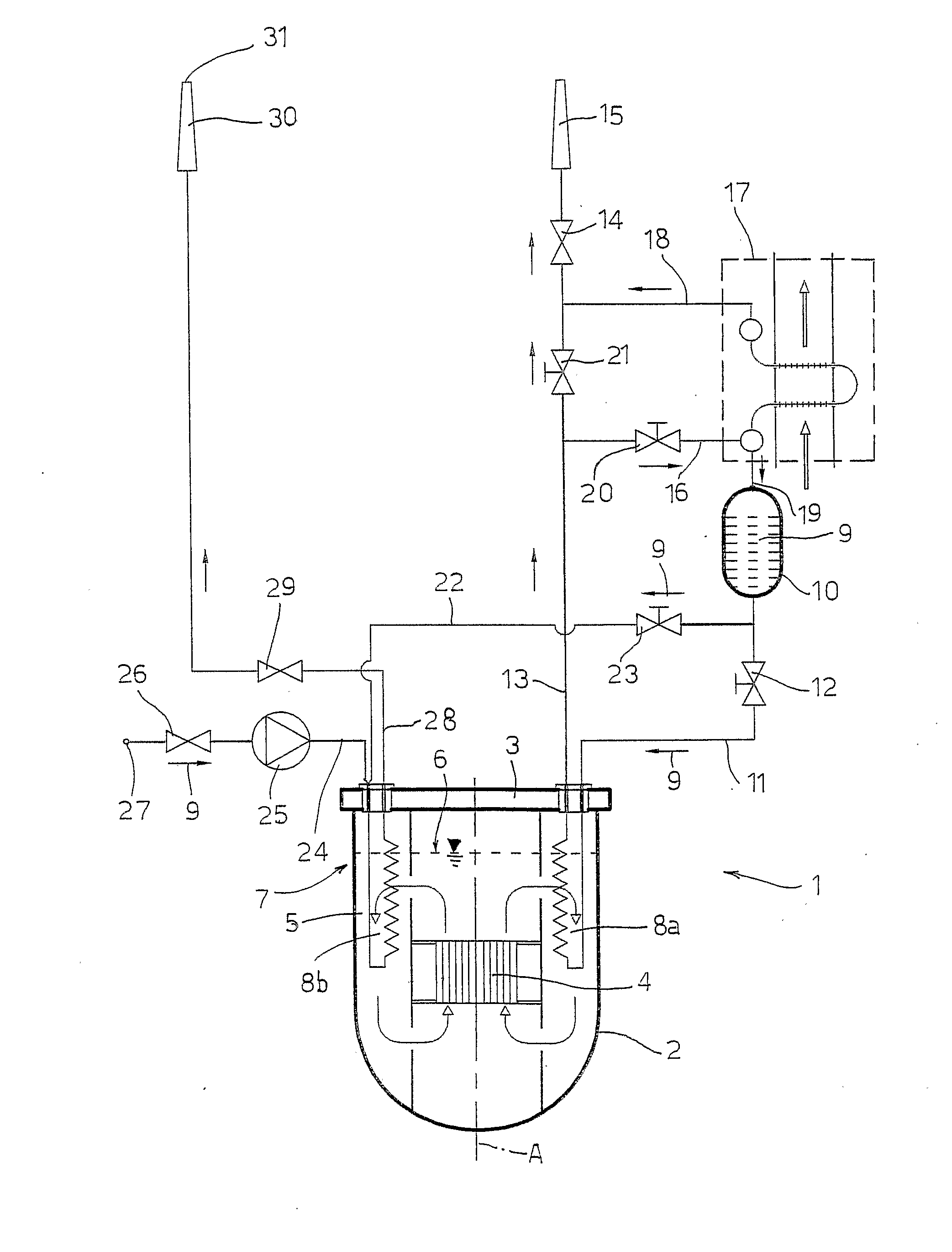
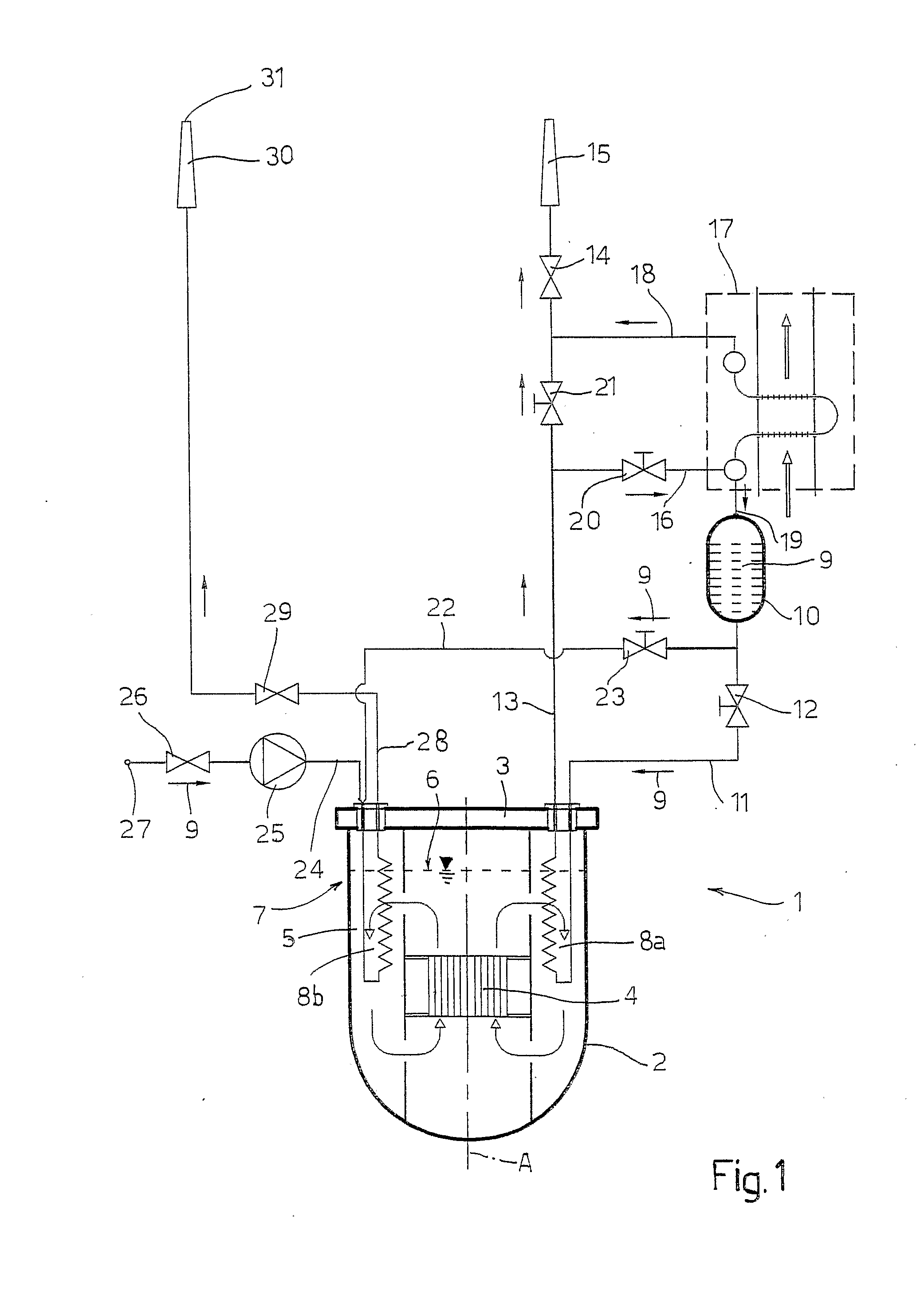
[0014]With reference to FIG. 1, a nuclear reactor 1 of a substantially known type, in particular a reactor using liquid metal or molten salts as primary cooling fluid, comprises a tank 2, which extends around a central axis A and is covered by a roof 3. Arranged within the tank 2 is a core 4, cooled by a primary fluid 5 (constituted, for example, by sodium, lead, lead-bismuth eutectic or molten salts), which fills the tank 2 up to a given height of the surface 6 of the fluid. Likewise housed in the tank 2 are primary heat exchangers, which transfer the power generated in the core 4 to a secondary circuit, as well as circulation pumps, machines for transfer of the fuel, and structures for supporting the instrumentation and control bars, none of which is represented in so far as they are not pertinent to the present invention.

[0015]The reactor 1 is provided with a system 7 for evacuation of the residual heat, comprising heat exchangers 8 housed circumferentially in the tank 2 and co-o...


PUM

PropertyMeasurementUnit
thermal conductivityaaaaaaaaaa
pressureaaaaaaaaaa
thicknessaaaaaaaaaa

Abstract

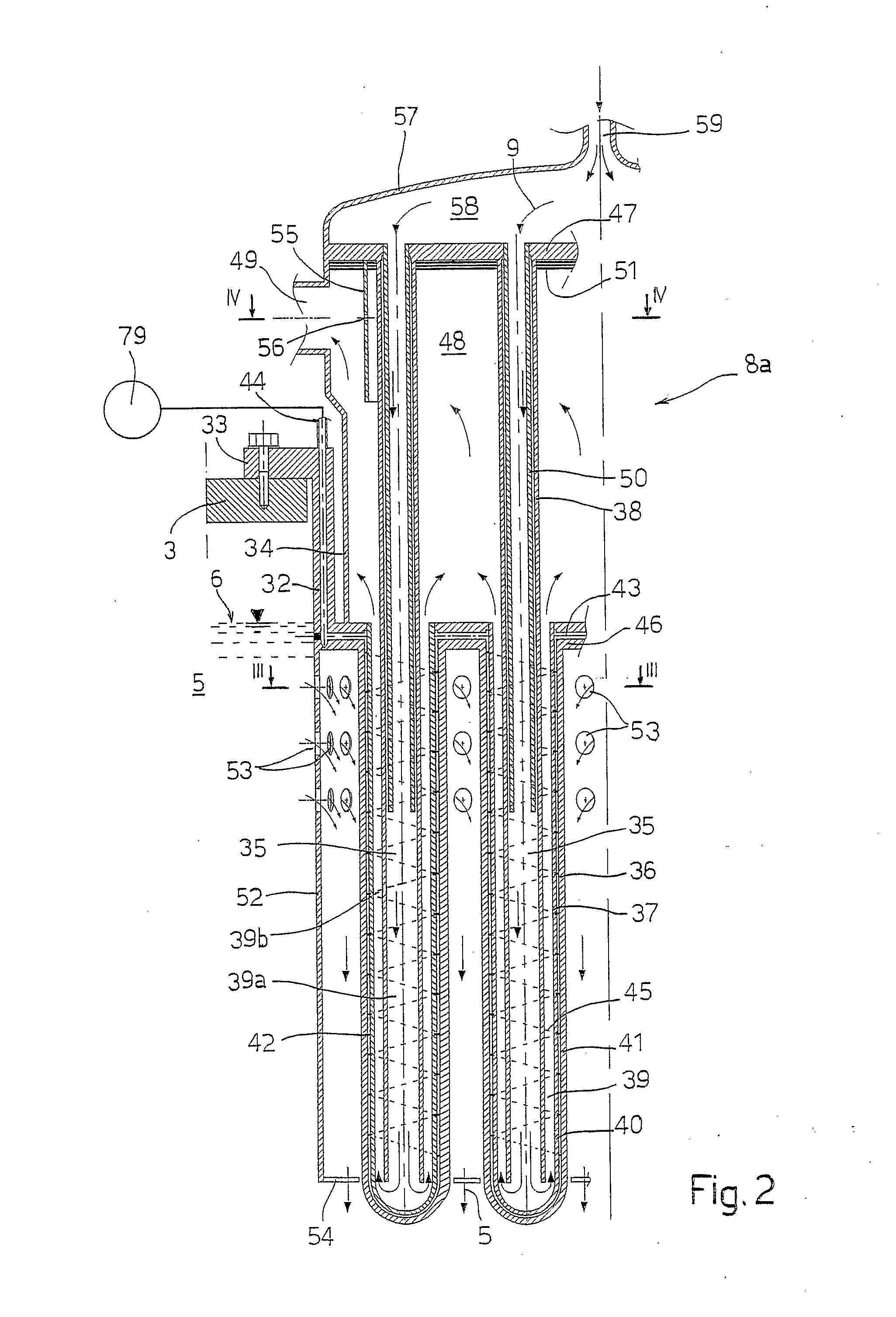
A system for evacuating the residual heat from a nuclear reactor cooled with liquid metal or molten salts has two types of heat exchangers immersed in the primary fluid of the reactor: heat exchangers with higher power density, which use boiling water as secondary cooling fluid and are particularly suitable for evacuating the residual heat in the first days after turning-off of the reactor; and heat exchangers operating with atmospheric air or with water and suitable for evacuating the residual heat for indefinite periods of time. Both types of heat exchangers present a bundle of heat-exchange elements, shaped in such a way that the secondary fluid circulating in each element is separated from the primary fluid of the reactor by a double wall of the element, which delimits a gap introduced in which is a pressurized inert gas having the function of continuous monitoring of the integrity of the heat exchanger and of thermal resistance calibrated for preventing solidification of the primary fluid of the reactor in the heat exchanger.

Description

TECHNICAL FIELD[0001]The present invention relates to a system for evacuating the residual heat from a liquid metal or molten salts cooled nuclear reactor.BACKGROUND ART[0002]It is known that in nuclear reactors there exists the need to evacuate the residual heat after stopping the reactor. For reasons of safety, the systems for evacuation of the residual heat must be particularly reliable and preferably diversified.[0003]In nuclear reactors that use water as primary cooling fluid, it is natural to use water also for the residual heat evacuation circuit, whilst for reactors that use primary cooling fluids other than water, in particular liquid metals or molten salts, the use of water is rendered problematical on account of the incompatibility between the two fluids, as in the case of sodium-cooled reactors, or of the risk of solidification of the primary fluid, as in general occurs in reactors cooled with liquid metal or molten salts.[0004]Consequently, auxiliary circuits operating ...

Claims


Application Information

Patent Timeline
Patent Type & Authority Applications(United States)
IPC IPC(8): G21C15/18
CPCF28D7/12F28F1/003Y02E30/35G21Y2002/206G21Y2004/30G21C15/182Y02E30/30
Inventor CINOTTI, LUCIANO
Owner DEL NOVA VIS
Learn More