
Separating device

a separation device and separating tube technology, applied in the direction of sealing/packing, drilling pipes, borehole/well accessories, etc., can solve the problems of reducing the effect of the sealing body and the elastic sealing elements, affecting the sealing effect, and reducing the drawbacks

Active Publication Date: 2012-08-07
SHCLUMBERGER NORGE AS
View PDF25 Cites 11 Cited by
  • Summary
  • Abstract
  • Description
  • Claims
  • Application Information

AI Technical Summary

Benefits of technology

[0006]NO 313712 describes a method and a system for separating water and drilling fluid. According to this document, a sealing body is fastened to the upper part of the drill string, above the hang-off tool, when the drill string is pulled up in order to attach the hang-off tool. The sealing body, together with the drill string to which it is fastened, is moved vertically in the riser by either the weight of the drill string or the vessel's drawworks and thereby displaces the fluid that is to be replaced. The sealing body is intended to seal against the inner wall of the riser, prevent the mixing of fluids and be moved in the longitudinal direction of the riser in that it is connected as a fixed element of the drill string, above the hang-off tool, and displaces the fluid that is to be replaced.
[0009]The aim of the present invention is to be able to remedy the disadvantages of the prior art as described above. One of the objects is to provide a method and a device which prevent the mixing of fluids in connection with the emptying of drilling fluid in a riser when the riser is disconnected from a wellhead. It is also an object to provide a device which eliminates the disadvantages, in the event that there are internal deposits in the riser, of having to run a scraper in a separate operation before the insertion of a fluid separating body. It is a further object to provide a solution which better utilises existing pipes in order to replace fluid in a riser. It is also an object to provide a solution that can be arranged at the point of use and quickly actuated or taken up again without being used.
[0022]By means of a method and device according to the invention it is possible to separate fluids in a riser during the replacement of, for example, drilling mud, without the fluids being mixed, whilst eliminating or reducing the drawbacks of the prior art.

Problems solved by technology

During drilling it is sometimes necessary to disconnect the riser from the wellhead and valve assembly, for example, because of bad weather or relocation of the drilling vessel.
When disconnecting the riser because of bad weather during drilling, the pipe portion that is below the wellhead will usually have a length that makes it impractical to pull up the entire length.
It is a problem that the water used to displace the drilling fluid mixes with the drilling fluid and contaminates it.
A portion of the drilling fluid must therefore, in order to be further usable, undergo a costly purification process or it must be destroyed.
There are several problems that may arise when using such a method and device.
When the rate of movement increases, the pressure against the sealing body and the elastic sealing elements will increase and be subjected to loads which may result in leakage and mixing of fluids in the riser.
The smaller pipes have a small internal diameter and require a great deal of energy to have fluids transported at high speed through the pipes.
This makes it difficult for the sealing body, together with the drill string, to supply sufficient energy for the displacement of the fluid inside the riser as they do not have sufficient mass.
The weight of the drill string is often also not sufficient to provide satisfactory pressure from the sealing body and a satisfactory rate of movement in the longitudinal direction of the riser.
Furthermore, it may be a problem that the inner walls of the riser are not prepared for sealing off high differential pressure across the sealing body.
The hoisting of the drill string results in the occurrence over time of tears in the surface which make sealing against a movable sealing body with high differential pressure difficult, and an optional scraping of the pipe wall prior to use of the sealing body will mean an additional running of the drill string in the riser, which is costly and time-consuming.
The vertical heave of the drilling vessel may also result in the same in that the sealing body is moved downwards in the riser but is stopped because the fluid that is below the sealing body and in the externally located smaller pipes cannot be returned quickly enough in relation to the vertical heave rate of the drilling vessel.
Thus, there are a number of disadvantages and potential problems with the prior art as described in NO 313712.

Method used


Image

  • Separating device
  • Separating device
  • Separating device

Examples


third embodiment

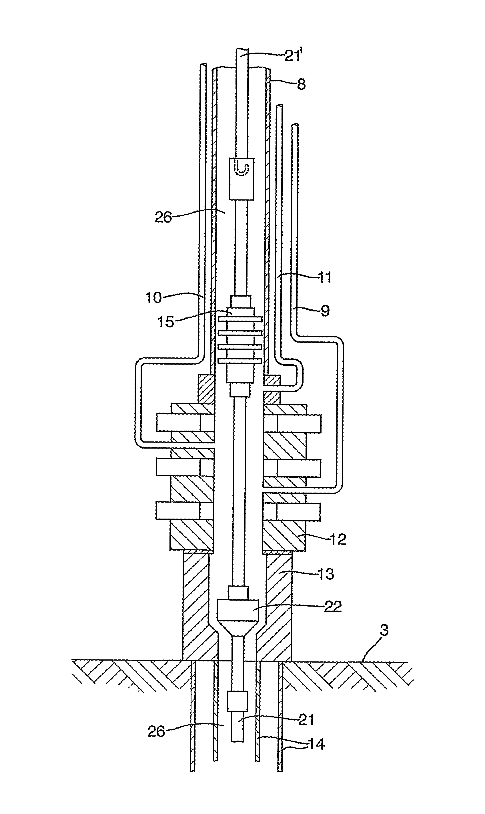
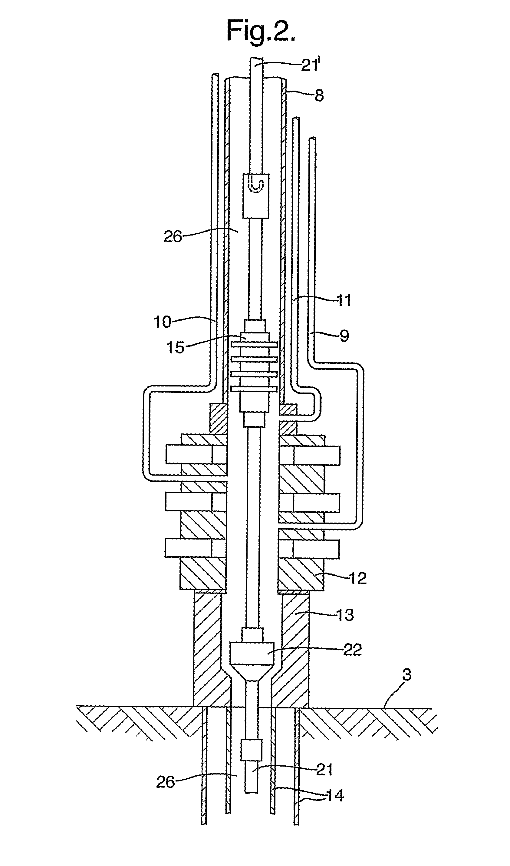
[0036]According to the embodiment shown in FIG. 3, the drilling vessel may now start the high-pressure pumps and begin to pump water down through the externally located longitudinal pipes (kill 9, choke 10& booster line 11) whilst the upper portion of the drill string 21′ is hoisted up onto the drilling vessel 1 at a desired speed. shown in FIG. 5, the installation device 27 will be hoisted up with the drill string 21′ at a desired speed.

[0037]The sealing element 15 according to the first embodiment shown in FIG. 3 can be disconnected from the drill string 21 and 21′ at the wellhead 13, whilst an assembly of sealing elements forms the seal against the internal pipe wall of the riser 8 and an actuatable mechanism closes the open flow area in the sealing body 15. Another variant is that the separating device 15 according to the third embodiment shown in FIG. 5 is mounted internally in the installation device 27, for example, by means of the externally located sealing elements / gaskets...

fifth embodiment

[0051]the invention is shown in FIGS. 7-10. The principles are the same as in the embodiments above and we will only describe the difference. When the hang-off tool 22 has been hung off in the wellhead 13 and disconnected, the pipe section 21′, where pipe section 21′ means, but is not limited to, a drill pipe, coil tubing or other elements having an internal open cavity, will be within the riser 8 in a condition where the pipe section 21′ has an open end above the wellhead 13 as shown in FIG. 7. In this position, an element / separating device 15 may be placed inside the pipe section 21′, which is of a character and configuration such that it is capable of being displaced internally or of moving inside the pipe section 21′ from the drill floor down to the open end above the wellhead 13 as shown in FIG. 8. This internal movement may be effected by pumping / displacement of the separating device 15 through the pipe section 21′. When the body 15 or the separating device is pumped out of th...


PUM


Abstract

The invention comprises a sealing body (15) separating device) which can be used to separate fluids in risers used in offshore oil production from drilling vessels at the sea surface. The invention is characterized in that the sealing body (15) can be placed in position above the wellhead (13) using several appropriate methods and, in an especially preferred application, by utilizing an installation tool (27) which is not sealing against the inner wall of the riser and which contains a suitable positioning means (28), and that the body (15) which forms a seal against the inner wall of the riser separates fluids during the replacement of drilling fluid with water and of water with drilling fluid. The body (15) can be displaced using hydraulic force upwards in the longitudinal direction of the riser in that fluid is pumped at a relatively high pressure down the externally located smaller pipes (9, 10, 11) of the riser. The body can be used while the drilling vessel (1) heaves relative to the seabed (3), and it is independent of the drilling vessel's drawers for the drill string (21) while the fluid is being replaced.

Description

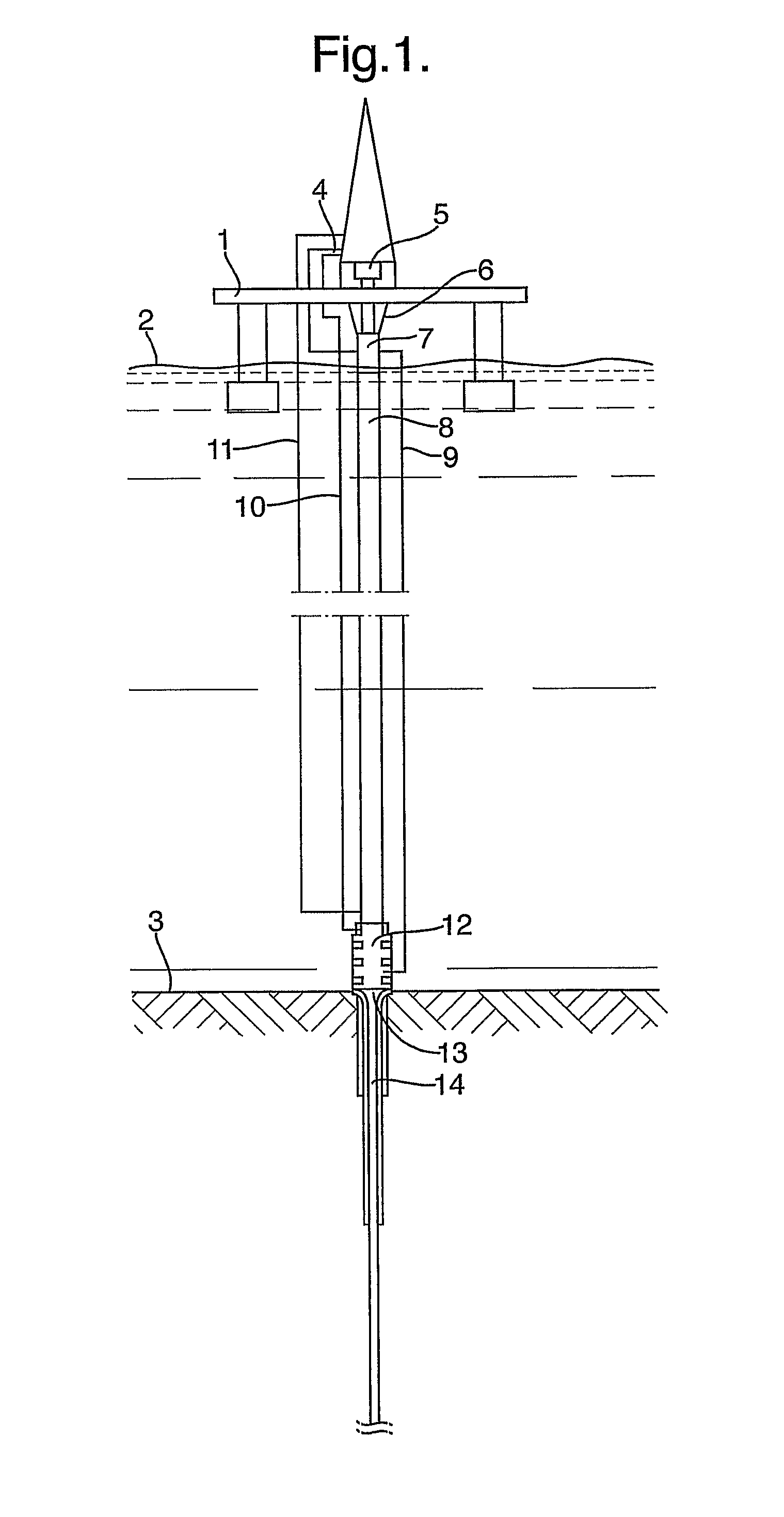
BACKGROUND AND SUMMARY OF THE INVENTION[0001]This invention relates to a method for preventing the mixing of fluids in a riser of the type used in offshore petroleum production. The invention also includes a device for carrying out the method.[0002]In offshore petroleum production, drilling vessels, as shown in FIG. 1, are used on the sea surface to drill wells in the seabed. A wellhead is installed on the seabed and is sealingly connected to the well casing and provided with the necessary valve assembly (BOP) and connecting devices to a riser which connects the wellhead to the drilling vessel at the sea surface. The riser is used in connection with the return and circulation of drilling fluids from the well and is normally filled with drilling fluid in the drilling phase. The riser is in addition equipped with longitudinal, externally located smaller pipes (choke, kill and optionally booster line) which are connected to a valve manifold on the drilling vessel. These pipes are used,...

Claims


Application Information

Patent Timeline
Patent Type & Authority Patents(United States)
IPC IPC(8): E21B23/00E21B33/035E21BE21B17/01E21B21/00
CPCE21B17/01E21B21/001E21B33/12
Inventor STOKKA, OYVINDKROHN, HELGE
Owner SHCLUMBERGER NORGE AS
Learn More