
Orthodontic appliance

a technology of orthodontic appliances and frankels, applied in the field of orthodontic appliances, can solve the problems of mixed results obtained by treating a class 3 malocclusion with such a frankel appliance, long time taken to achieve reasonable correction of a class 3 malocclusion, and insufficient dimensional tolerance. , to achieve the effect of reducing the web profile, reducing the treatment cos

Inactive Publication Date: 2010-09-09
FARRELL CHRISTOPHER JOHN
View PDF26 Cites 20 Cited by
  • Summary
  • Abstract
  • Description
  • Claims
  • Application Information

AI Technical Summary

Benefits of technology

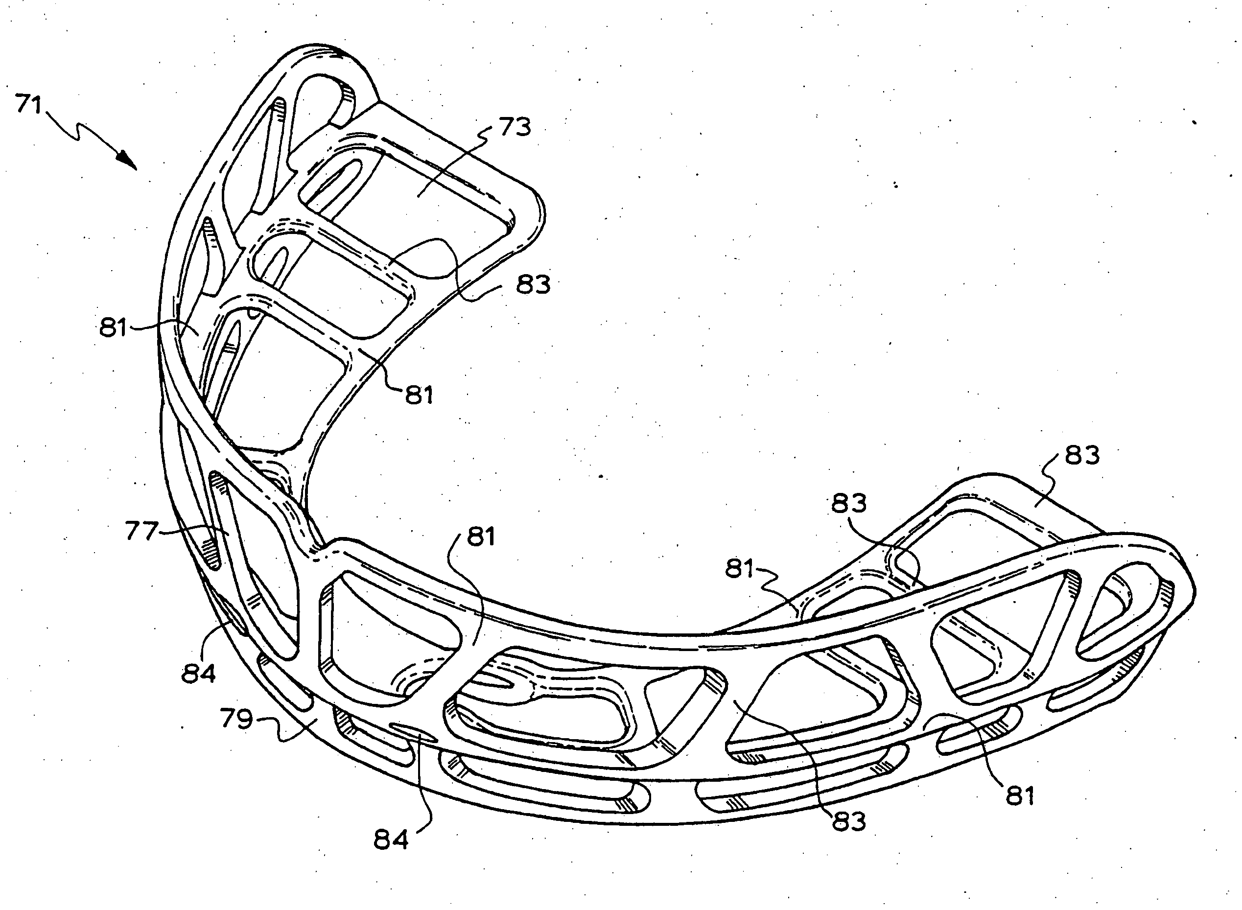
[0021]The mounting arrangement may be resiliently flexible. In particular the outer and inner walls and the web may be able to flex resiliently when the arms are moved or displaced out of a resting position, e.g. corresponding to a desired arch form, to accommodate a different arch width in a user, e.g. a narrow upper arch. The deformed walls and the web may apply a return force to the arch tending to return it to the resting position. The resilience of the inner and outer walls may also assist in fitting the appliance to the arch and teeth.
[0083]The mounting arrangement may have an incisor region and two arms extending back from the incisor region that extend across the canines and molars of the upper arch of a user, and the mounting arrangement may be resiliently flexible to enable the arms to be moved towards and away from each other to some extent to accommodate different arch sizes. The resiliently flexible mounting arrangement also helps the mounting arrangement to be fitted onto the arch and teeth of a user.

Problems solved by technology

This is caused by a lack of development in the lower jaw of a user resulting in a lower jaw with a smaller arch than the upper jaw.
However this treatment is very aggressive and invasive.
However the results obtained by treating a Class 3 malocclusion with such a Frankel appliance have been mixed.
Further the time taken to achieve reasonable correction of a Class 3 malocclusion can often be very lengthy.

Method used


Image

  • Orthodontic appliance
  • Orthodontic appliance
  • Orthodontic appliance

Examples


Embodiment Construction

[0106]An orthodontic appliance for treating inter alia a Class 3 malocclusion in accordance with this invention may manifest itself in a variety of forms. It will be convenient to hereinafter describe at least one embodiment of the invention in detail with reference to the accompanying drawings. The purpose of providing this detailed description is to instruct persons having an interest in the subject matter of the invention how to carry the invention into practical effect. However it is to be clearly understood that the specific nature of this detailed description does not supersede the generality of the preceding broad description. In the drawings:

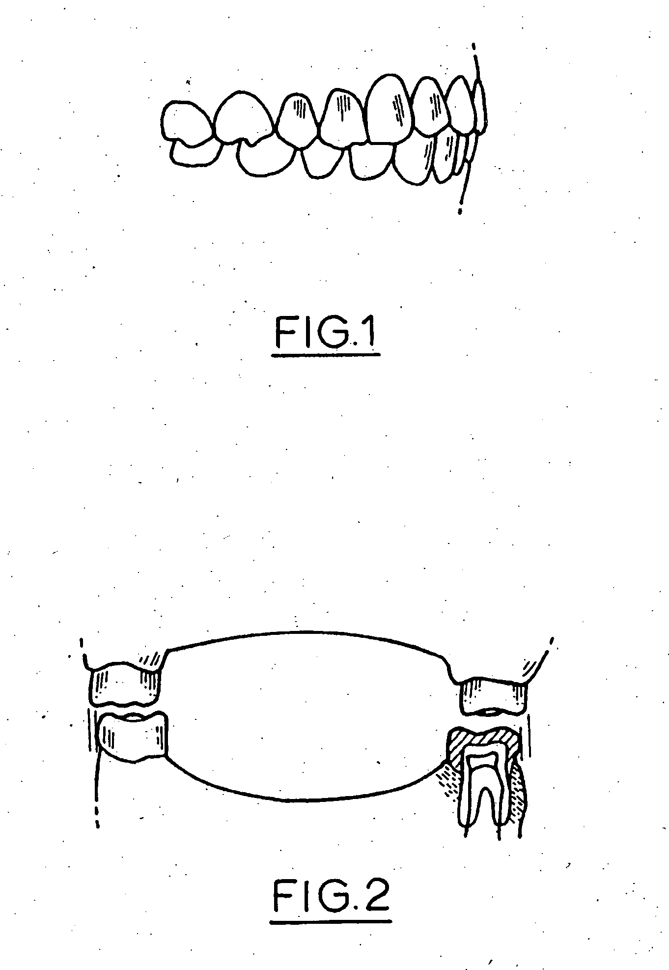
[0107]FIG. 1 is a schematic side view of a dental model showing correct dental occlusion;

[0108]FIG. 2 is a schematic rear view of the model of FIG. 1 showing correct dental occlusion;

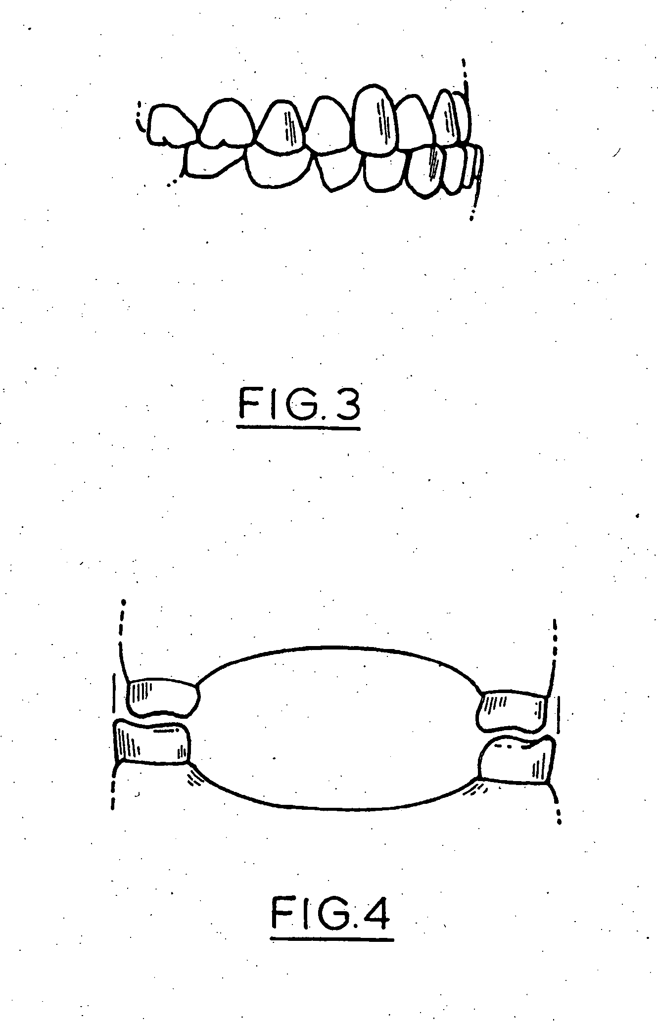
[0109]FIG. 3 is a schematic side view of a dental model showing a Class 3 malocclusion with the incisor teeth of the lower arch positioned proud of the inci...


PUM


Abstract

An orthodontic appliance that is particularly useful for correcting a class occlusion is disclosed. The appliance includes a mounting arrangement for mounting over an upper arch of a user having a front region and two arm regions extending rearward from the front region. The mounting arrangement includes an outer wall and an inner wall and a web extending there between. The outer wall, the web and the inner wall collectively define an upper channel within which the upper arch and teeth of a user are received to mount the appliance. They also define a lower channel for receiving the lower arch and teeth. The outer wall has an upper portion spaced forward of the upper arch teeth and gums forming an outer spacing formation for holding the buccal mucosa away therefrom. The appliance also includes a tongue elevator on a lower portion of the inner wall for raising position corresponding to an arch form will tend to return to the desired arch form. Further the resilient flexibility assists fitting of the appliance.

Description

FIELD OF THE INVENTION[0001]This invention relates to an orthodontic appliance.[0002]This invention relates particularly but not exclusively to an active orthodontic appliance for use in the treatment of a Class 3 malocclusion. It will therefore be convenient to hereinafter describe the invention with reference to this example application. However at the same time it is to be clearly understood that the invention is capable of broader application. For example the appliance may also have application in the treatment of other conditions and other types of malocclusions. Further the orthodontic appliance can also be used as a functional orthodontic appliance and as a passive orthodontic appliance.BACKGROUND TO THE INVENTION[0003]Humans have an upper jaw called a maxilla forming an upper arch and a hinged lower jaw called a mandible forming a lower arch. A patient has correct dental occlusion when the upper arch matches the size and shape of the lower arch such that the teeth of the upp...

Claims


Application Information

Patent Timeline
IPC IPC(8): A61C7/08
CPCA61C7/08A61C7/10A61C7/36
Inventor FARRELL, CHRISTOPHER JOHN
Owner FARRELL CHRISTOPHER JOHN
Learn More