Adapter for coupling a laser processing device to an object

a laser processing device and adapter technology, applied in the field of adapters for coupling laser processing devices to objects, can solve the problems of reducing the image quality with which the object field can be observed, and the requirement for reflecting surfaces to be located near an image plane can usually not be satisfied, so as to achieve the effect of low manufacturing cos

Active Publication Date: 2010-09-09
CARL ZEISS MEDITEC AG
View PDF42 Cites 32 Cited by
  • Summary
  • Abstract
  • Description
  • Claims
  • Application Information

AI Technical Summary

Benefits of technology

[0009]As the illumination necessary for visual observation, the use of a light source whose radiation passes through the laser processing device could be contemplated. However, since the optics provided therein usually comprise a multiplicity of interfaces all having a certain residual reflectivity, a non-negligible part of the illumination radiation inevitably cross-talks into the image of the object field. Depending on the optical arrangement, this is noticeable in the image plane as global brightening of the image or as bright spots at fixed sites of the observed object field, especially at its center. In any case, the reflections reduce the image quality with which the object field can be observed.
[0031]Suitable LEDs are white-light LEDs or color LEDs. In the case of color LEDs, it is convenient to gather LEDs in groups, e.g. to assemble each group from red, green and blue LEDs. If the red, green and blue LEDs are individually controllable, the color temperature of illumination may be adjusted via such control. This makes it possible to particularly emphasize certain structures, such as blood vessels, for example, by changing the color temperature of the illumination radiation, e.g. to green illumination.

Problems solved by technology

However, since the optics provided therein usually comprise a multiplicity of interfaces all having a certain residual reflectivity, a non-negligible part of the illumination radiation inevitably cross-talks into the image of the object field.
In any case, the reflections reduce the image quality with which the object field can be observed.
However, the condition that all reflecting surfaces should be located near an image plane can usually not be satisfied by an adapter of the aforementioned type, because its central region is inevitably located in the beam path, and the position of the adapter and, consequently, of the possibly reflecting surfaces is given by the type of the object and is, thus, hardly variable and, in particular, not optimally selectable under optical aspects.

Method used


Image

  • Adapter for coupling a laser processing device to an object
  • Adapter for coupling a laser processing device to an object
  • Adapter for coupling a laser processing device to an object

Examples


Embodiment Construction

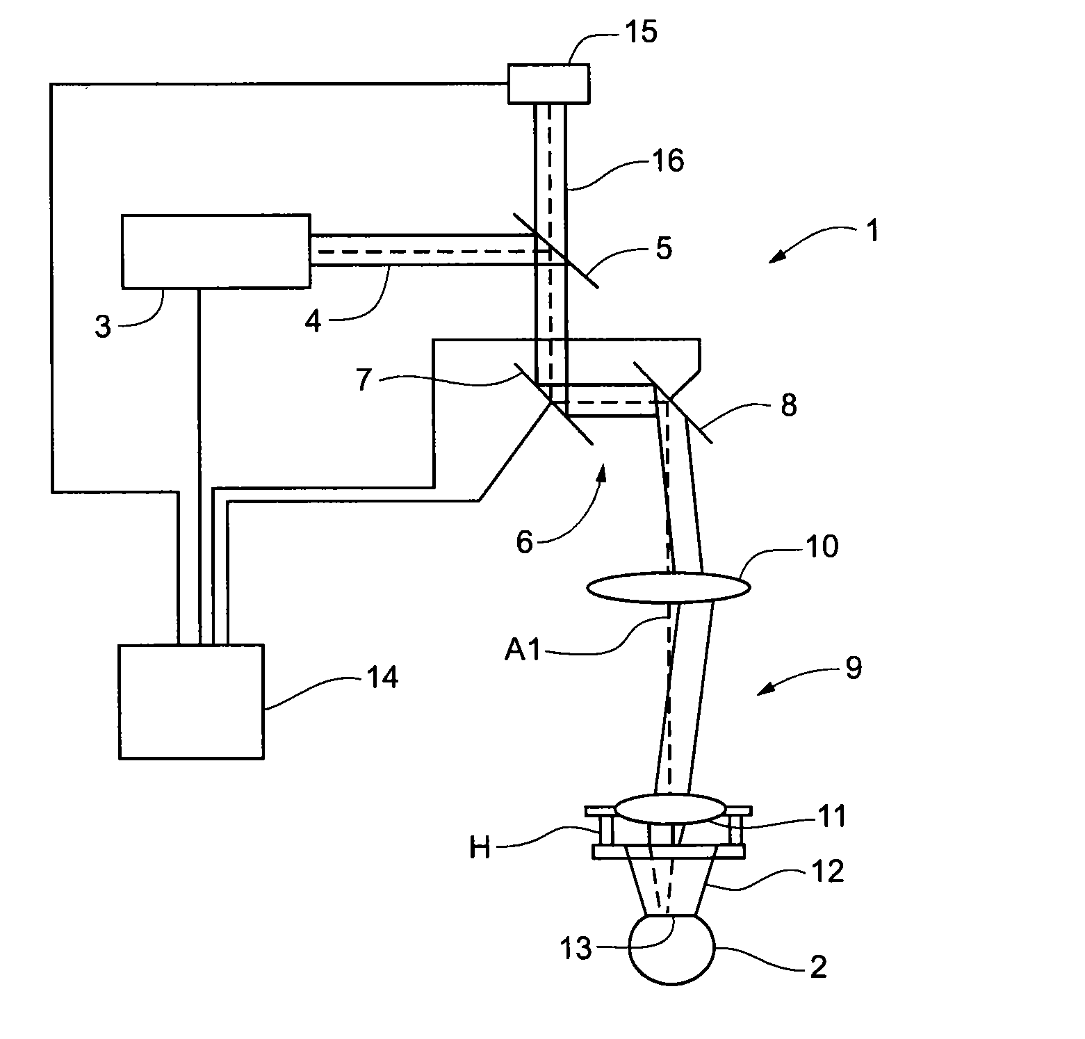
[0044]The treatment apparatus 1 of FIG. 1 serves to effect correction of defective eyesight on the eye 2 of a patient according to the known LASIK method. For this purpose, the treatment apparatus 1 comprises a laser 3 which emits pulsed laser radiation. The pulse duration is e.g. in the femtosecond range, and the laser radiation acts by means of non-linear optical effects in the cornea in the manner described above. The treatment beam 4 emitted by the laser 3 along an optical axis A1 is incident on a beam splitter 5 which guides the treatment beam 4 to a scanning unit 6. The scanning unit 6 comprises two scanning mirrors 7 and 8 which are rotatable about mutually orthogonal axes such that the scanning unit 6 two-dimensionally deflects the treatment beam 4. Adjustable projection optics 9 focuses the treatment beam 4 onto or into the eye 2. The projection optics 9 comprises two lenses 10 and 11. The treatment apparatus 1 represents a laser processing device.

[0045]Following the lens 1...


PUM


Abstract

An adapter contact lens to be applied in contact with an anterior corneal surface. The adapter includes a contact glass portion having a corneal contact surface curvature that is flatter than that of the undeformed anterior corneal surface. When the contact glass is applied the cornea deforms assume a deformed state corneal curvature that is parallel to the flatter corneal contact surface curvature. A mount portion circumferentially surrounds the contact glass and defines a suction duct that is structured to secure the adapter to the cornea by negative pressure when it is brought into contact with a surface of the eye surrounding the contact glass portion. The suction duct being partially defined by a peripheral edge of the mount; that extends outwardly away from the mount portion and toward but not intersecting or extending beyond a geometric continuation of the corneal contact surface curvature.

Description

CLAIM TO PRIORITY[0001]This application is a divisional application of U.S. patent application Ser. No. 10 / 579,439 entitled “Adapter for Coupling a Laser Processing Device to an Object”, filed Feb. 27, 2007, which is a national stage entry of PCT / EP2004 / 011785 filed Oct. 18, 2004, which claims priority to German patent application DE 10353264.1 filed Nov. 14, 2003 all of which are incorporated by reference in their entirety herein.FIELD OF THE INVENTION[0002]The invention relates to an adapter for coupling a laser processing device to an object, said adapter comprising a central region which can be switched into the beam path of the laser processing device, an illumination beam path through which the illumination radiation for illumination of an object field detectable by the central region can be guided, and a peripheral region located outside the central region, by which peripheral region the adapter can be mounted on the object and / or on the laser processing device.BACKGROUND OF ...

Claims


Application Information

Patent Timeline
Patent Type & Authority Applications(United States)
IPC IPC(8): A61F9/009A61B19/00A61F9/01
CPCA61B19/5202A61B2017/306A61B2019/5206A61F2009/00872A61F9/00827A61F9/009A61B2019/521A61B90/30A61B2090/309A61B2090/306
Inventor MUHLHOFF, DIRKEBERT, ELKEFESTAG, KARSTENWOLF, UWE
Owner CARL ZEISS MEDITEC AG
Why Eureka
Try Eureka