
Device and a method for preparing an ophthalmic lens for machining

a technology of ophthalmic lenses and machining methods, which is applied in the field of eyeglasses, can solve the problems of loss of the frame of reference of the support and/or the manipulator arm, affecting the accuracy of the blocking accessory, and the inability of the stepper motor to determine the exact number of steps performed

Active Publication Date: 2010-09-09
ESSILOR INT CIE GEN DOPTIQUE
View PDF13 Cites 23 Cited by
  • Summary
  • Abstract
  • Description
  • Claims
  • Application Information

AI Technical Summary

Benefits of technology

[0022]Finally, inaccuracies while making and assembling the parts of the preparation device, and the ways in which these parts vary over time (wear, impacts, temperature variations, . . . ) all contribute to reducing the accuracy with which the blocking accessory is placed on the lens.
[0082]When the blocking accessory has been placed on the lens and the manipulator arm moves back up, the blocking accessory needs to disengage from the arm without force in order to avoid the blocking accessory moving over the front face of the lens. If the blocking accessory is inclined, the conical shape of its base avoids the base rubbing against the bore in the reception head of the manipulator arm while the arm is rising.

Problems solved by technology

In investigations carried out by the Applicant, it has been found that when the support and / or the manipulator arm is caused to move quickly, stepper motors are not capable of determining the exact number of steps performed.
Such “step loss” then gives rise to a loss of the frame of reference of the support and / or the manipulator arm, and that is harmful to the accuracy with which the blocking accessory is placed on the lens and thus to the accuracy with which said lens is centered.
Furthermore, even at moderate speed, such motors generally provide data that is very slightly erroneous.
These errors are due to the way in which such motors are designed and they tend to become worse over time.

Method used


Image

  • Device and a method for preparing an ophthalmic lens for machining
  • Device and a method for preparing an ophthalmic lens for machining
  • Device and a method for preparing an ophthalmic lens for machining

Examples


Embodiment Construction

[0093]The description below with reference to the accompanying drawings of an embodiment given by way of non-limiting example makes it clear what the invention consists in and how it can be reduced to practice.

IN THE ACCOMPANYING DRAWINGS

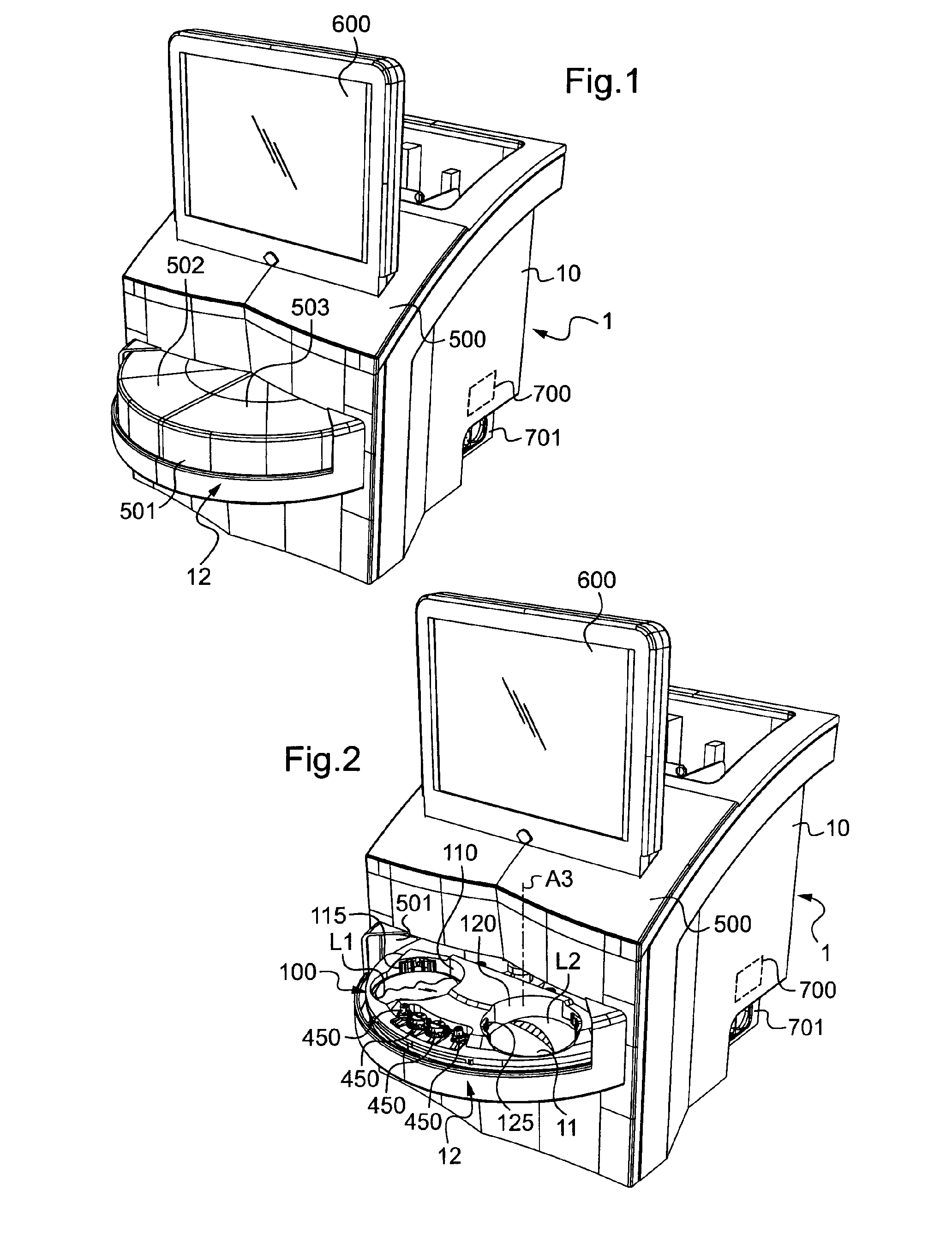
[0094]FIG. 1 is an overall perspective view of the outside of an ophthalmic lens preparation device of the invention, the device being provided with a hood;

[0095]FIG. 2 is a view similar to FIG. 1, with an access door of the hood being open to enable a pair of ophthalmic lenses and blocking accessories to be loaded on and / or unloaded from a support of the device;

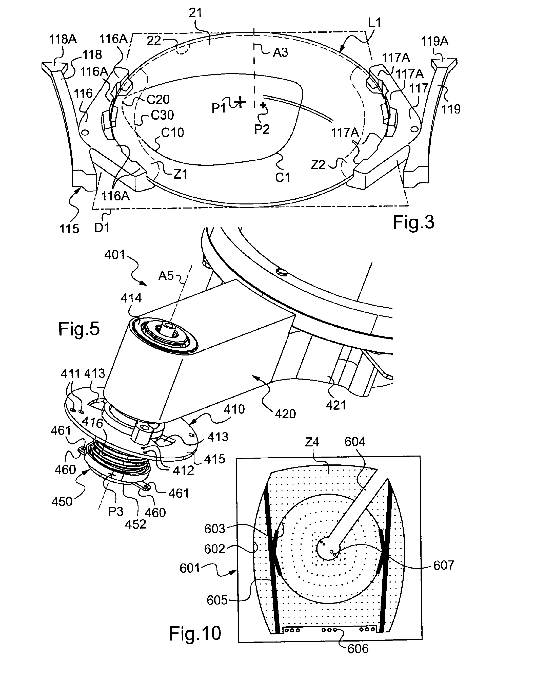
[0096]FIG. 3 is a perspective view of clamping jaws for holding an ophthalmic lens, enabling the ophthalmic lens to be loaded onto and held on the FIG. 2 support;

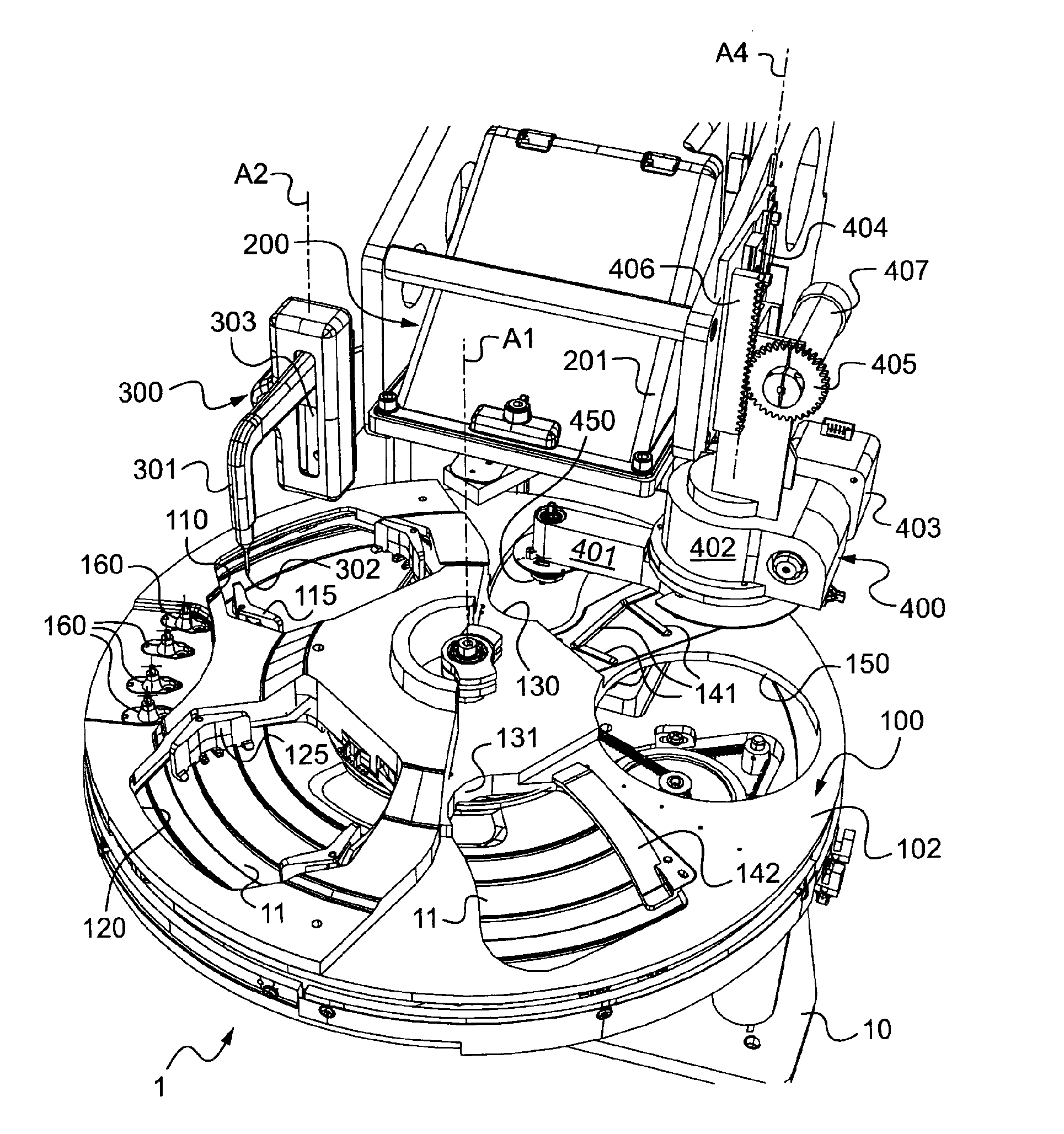
[0097]FIG. 4 is a perspective view of the inside of the FIG. 1 preparation device fitted with its support, with an image acquisition device, and with a manipulator arm, and shown in a configuration of the support and of the manipula...


PUM


Abstract

A preparation device (1) for preparing an ophthalmic lens to be machined, includes a support (100) suitable for holding the ophthalmic lens, blocking elements (400) including at least one blocking accessory (450) and a manipulator arm (401) for manipulating the blocking accessory, an acquisition device (200) suitable for acquiring an image of the ophthalmic lens, electronic and / or computer processor elements (700) suitable firstly for deducing an optical frame of reference of the ophthalmic lens, and secondly for controlling the position of the manipulator arm and / or of the support to apply the blocking accessory against the ophthalmic lens in a given blocking position. The blocking elements and / or the support include at least one marker element and the electronic and / or computer processor elements are adapted to identify the position of the marker element in an image acquired by the acquisition device, in which image there appears an image of the marker element.

Description

TECHNICAL FIELD TO WHICH THE INVENTION RELATES AND TECHNOLOGICAL BACKGROUND[0001]The present invention relates in general to the field of eyeglasses and more particularly to preparing an ophthalmic lens for shaping by edging.[0002]More particularly, the invention relates to a device for preparing an ophthalmic lens for machining, the device comprising:[0003]a support suitable for holding said ophthalmic lens;[0004]blocking means including at least one blocking accessory and a manipulator arm for manipulating said blocking accessory;[0005]an acquisition device suitable for acquiring an image of the ophthalmic lens held by the support; and[0006]electronic and / or computer processor means suitable firstly for deducing an optical frame of reference of the ophthalmic lens from the image acquired by the acquisition device, and secondly for controlling the position of the manipulator arm and / or of the support to apply said blocking accessory against the ophthalmic lens in a given blocking p...

Claims


Application Information

Patent Timeline
IPC IPC(8): G05D3/12
CPCB24B9/146
Inventor BRECHEMIER, BERNARDBOUTINON, STEPHANEBARANTON, KONOGAN
Owner ESSILOR INT CIE GEN DOPTIQUE
Learn More