
Cooling channel formed in a wall

a cooling channel and wall technology, applied in the direction of machine/engine, manufacturing tools, solventing apparatus, etc., can solve the problems of long and expensive operation, particularly complex shape of the electrode, and the inability to form a channel by electroerosion using known methods, and achieve the effect of reducing costs

Active Publication Date: 2010-09-16
SN DETUDE & DE CONSTR DE MOTEURS DAVIATION S N E C M A
View PDF12 Cites 7 Cited by
  • Summary
  • Abstract
  • Description
  • Claims
  • Application Information

AI Technical Summary

Benefits of technology

[0006]An object of the invention is thus to provide an alternative to known methods, making it possible to form a cooling channel of the above-specified type, more quickly and at lower cost.
[0011]Nevertheless, if it is desired to perform the piercing and the diffusion portion by electroerosion, then two different electrodes are used for each of said portions. The electrodes are simpler in shape than the electrodes that have been used in the past, so they are easier and less expensive to make. For example, for the piercing, it is possible to use an electrode that is cylindrical.
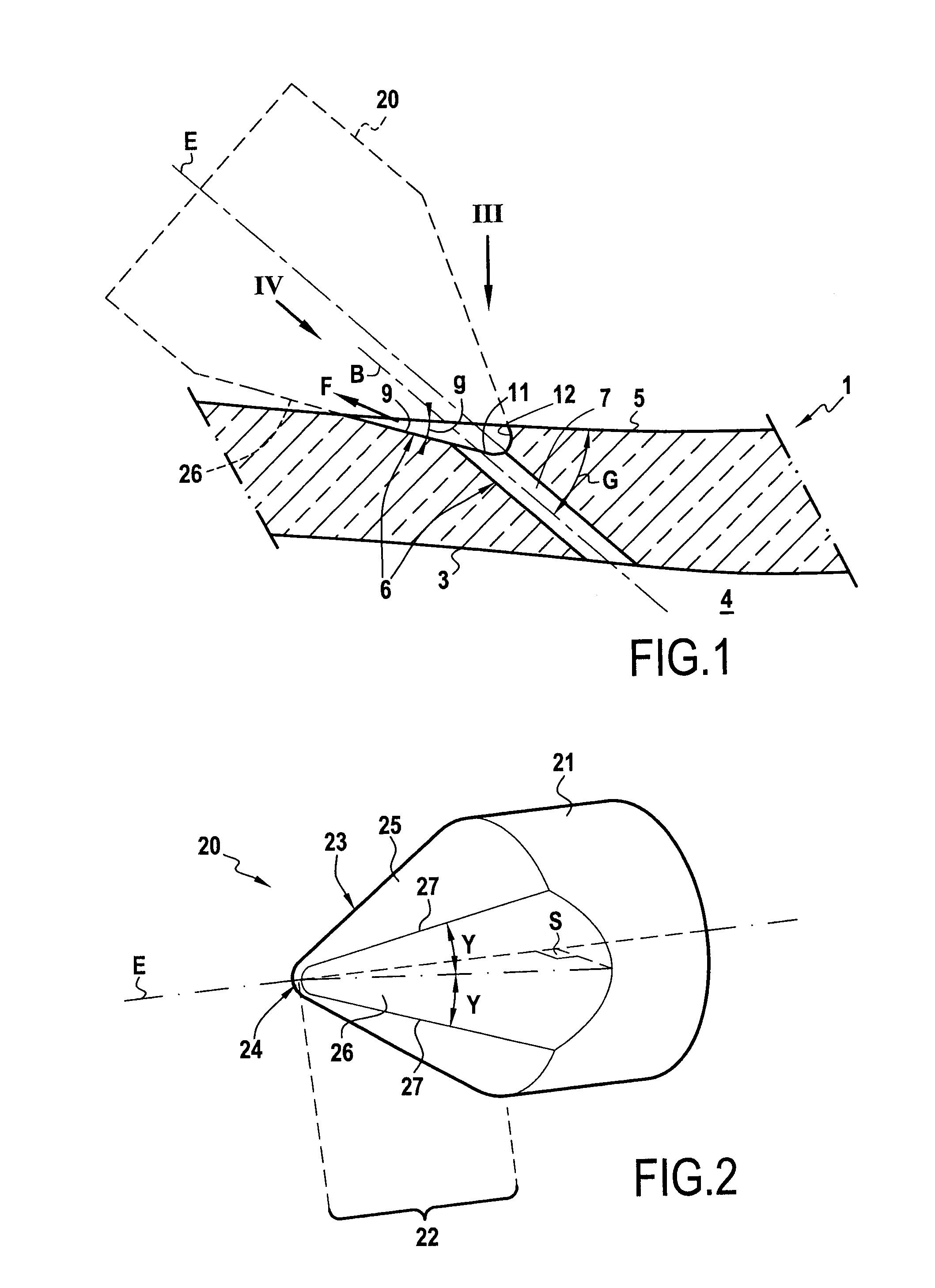
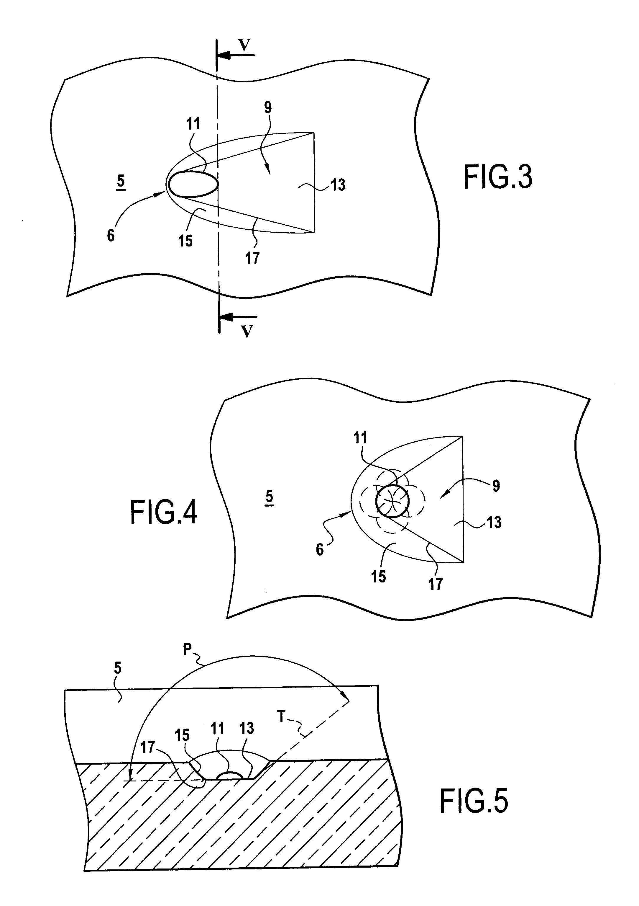
[0013]The above-specified shape for the electrode makes it possible firstly to avoid creating a sharp angle in the bottom of the diffusion portion, where sharp angles generally constitute starter zones for cracks.
[0014]Secondly, an electrode of that shape and of appropriate dimensions relative to the hole makes it possible to form a diffusion portion of a shape that is sufficiently broad and flared to ensure that, given the tolerances involved in making the hole and the diffusion portion, and regardless of the position of the hole relative to the diffusion portion, the diffusion portion provides good diffusion (i.e. good guidance and good spreading) of the stream of air leaving the hole.
[0017]Advantageously, the angle formed between the margin and the front end of the bottom in a plane perpendicular to the bottom is not “sharp” in the sense that it is strictly greater than 90°. This avoids creating crack-starter zones.

Problems solved by technology

As can be seen, the shape of that electrode is particularly complex.
In addition, in general manner, forming a channel by electroerosion using known methods remains an operation that is lengthy and expensive.

Method used


Image

  • Cooling channel formed in a wall
  • Cooling channel formed in a wall
  • Cooling channel formed in a wall

Examples


Embodiment Construction

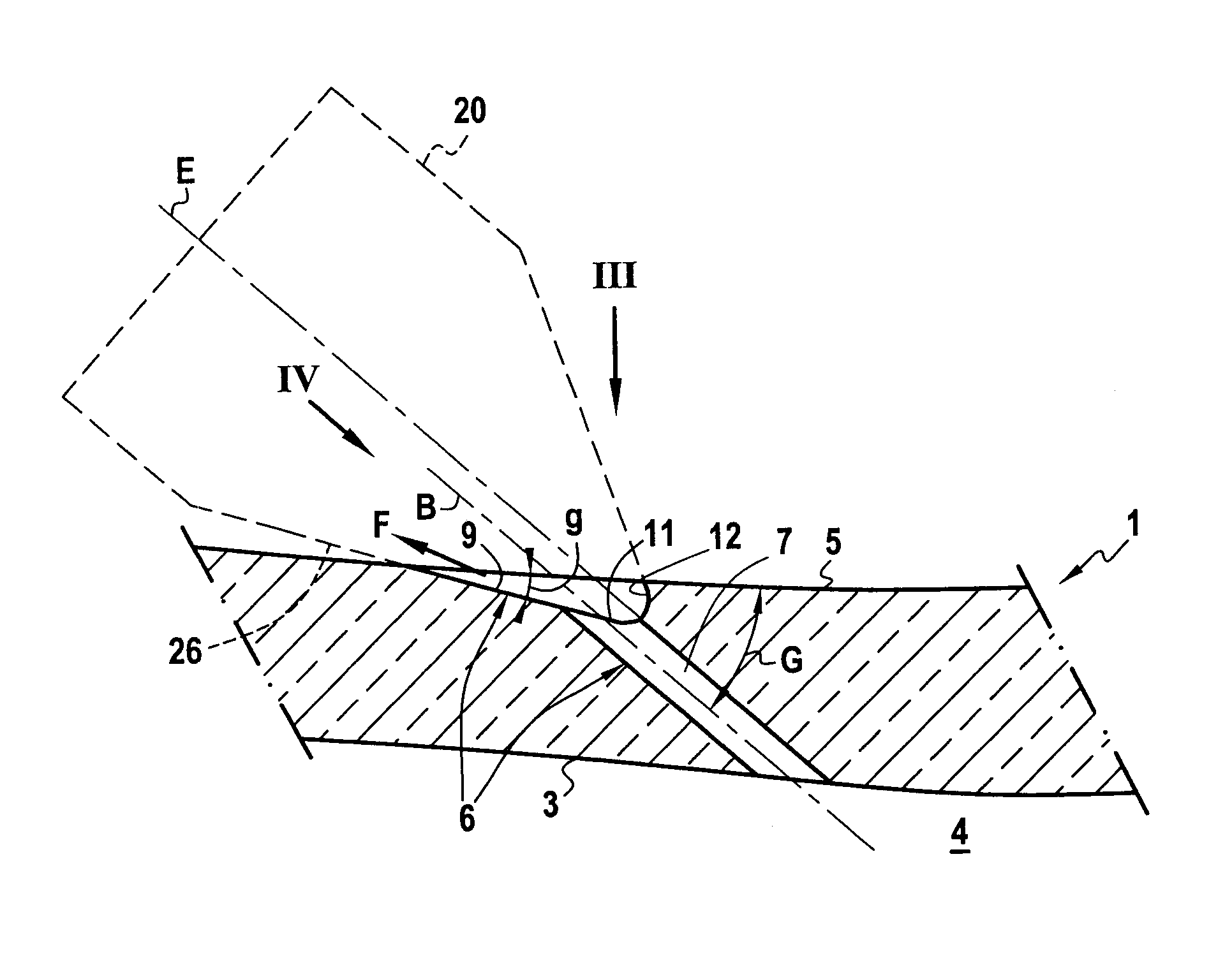
[0025]With reference to FIGS. 1, 3, 4, and 5, there follows a description of an example of a wall element of the invention.

[0026]Said wall element presents an inside surface 3 and an outside surface 5. This element belongs to a wall 1 of a hollow gas-turbine blade, such as a high pressure turbine blade of a turbojet. This type of hollow blade has an internal cooling passage 4 defined in part by the inside surface 3, said passage being fed with cool air.

[0027]The outside surface 5 of the wall is subjected to the hot gas passing through the turbine and it therefore needs to be cooled. For this purpose, cooling channels are provided in the wall 1. At least some of these channels are of the same type as the channel shown in FIG. 1. This channel 6 passes cool air coming from the internal cooling passage 4 of the blade and delivers this cool air to the outside surface 5 in order to cool it. The channel 6 comprises two portions: an adjustment portion formed by a hole 7, and a diffusion por...


PUM

PropertyMeasurementUnit
angleaaaaaaaaaa
angleaaaaaaaaaa
angleaaaaaaaaaa

Abstract

A wall in which there is formed at least one cooling channel, said wall being cooled by cool air flowing in the channel, the channel comprising a hole and a diffusion portion, the hole opening out at one end into the inside surface of the wall, and at its other end into the diffusion portion where it forms an orifice, the diffusion portion flaring around said orifice and opening out into the outside surface of the wall, the diffusion portion having a bottom whose front end is substantially plane, sloping, and extending in front of the orifice, and also having a margin extending behind, round the sides, and in front of the orifice, said margin joining the sides of the front end. A method and an electrode for making such a cooling channel. A turbomachine blade presenting such a wall.

Description

[0001]This application is a divisional of U.S. application Ser. No. 11 / 492,110 filed Jul. 25, 2006, the entire contents of which is incorporated herein by reference, and claims the benefit of priority under 35 U.S.C. 119 to French Application No. 0507924 filed Jul. 26, 2005 and French Application No. 0650103 filed Jan. 12, 2006.[0002]The invention relates to a method of forming a cooling channel in a wall, to an electrode used for implementing the method, to a wall element in which a cooling channel is formed, and to a hollow turbomachine blade including a wall element of this type.FIELD OF THE INVENTION[0003]More precisely, the invention relates to a wall element of the type comprising an inside surface and an outside surface, the outside surface being suitable for being cooled by cool air flowing in said cooling channel. In addition, the cooling channel is of the type comprising a hole and a diffusion portion, the hole opening out at one end into the inside surface of the wall and...

Claims


Application Information

Patent Timeline
Patent Type & Authority Applications(United States)
IPC IPC(8): B23P15/02
CPCF01D5/186B23H9/10F05D2250/232Y10T29/49341F05D2230/13B23H1/04Y10T29/49336F05D2230/12B23K35/0216
Inventor CAMHI, EMMANUEL PIERRECROUILBOIS, LAURENTPIERRE, MAREIX JEANPASQUIET, DIDIER
Owner SN DETUDE & DE CONSTR DE MOTEURS DAVIATION S N E C M A
Learn More