Fuel injection systems in a turbomachine combustion chamber

a technology of fuel injection system and combustion chamber, which is applied in the direction of machines/engines, mechanical equipment, lighting and heating apparatus, etc., can solve problems such as unsatisfactory solutions, and achieve the effect of simple, effective and economi

Active Publication Date: 2010-09-16
SN DETUDE & DE CONSTR DE MOTEURS DAVIATION S N E C M A
View PDF6 Cites 10 Cited by
  • Summary
  • Abstract
  • Description
  • Claims
  • Application Information

AI Technical Summary

Benefits of technology

[0007]The invention in particular has for purpose to provide a simple, effective and economic solution to this problem.

Problems solved by technology

However, this solution is not entirely satisfactory since it does not make it possible to improve the propagation of the flame to the other pools.

Method used


Image

  • Fuel injection systems in a turbomachine combustion chamber
  • Fuel injection systems in a turbomachine combustion chamber
  • Fuel injection systems in a turbomachine combustion chamber

Examples


Embodiment Construction

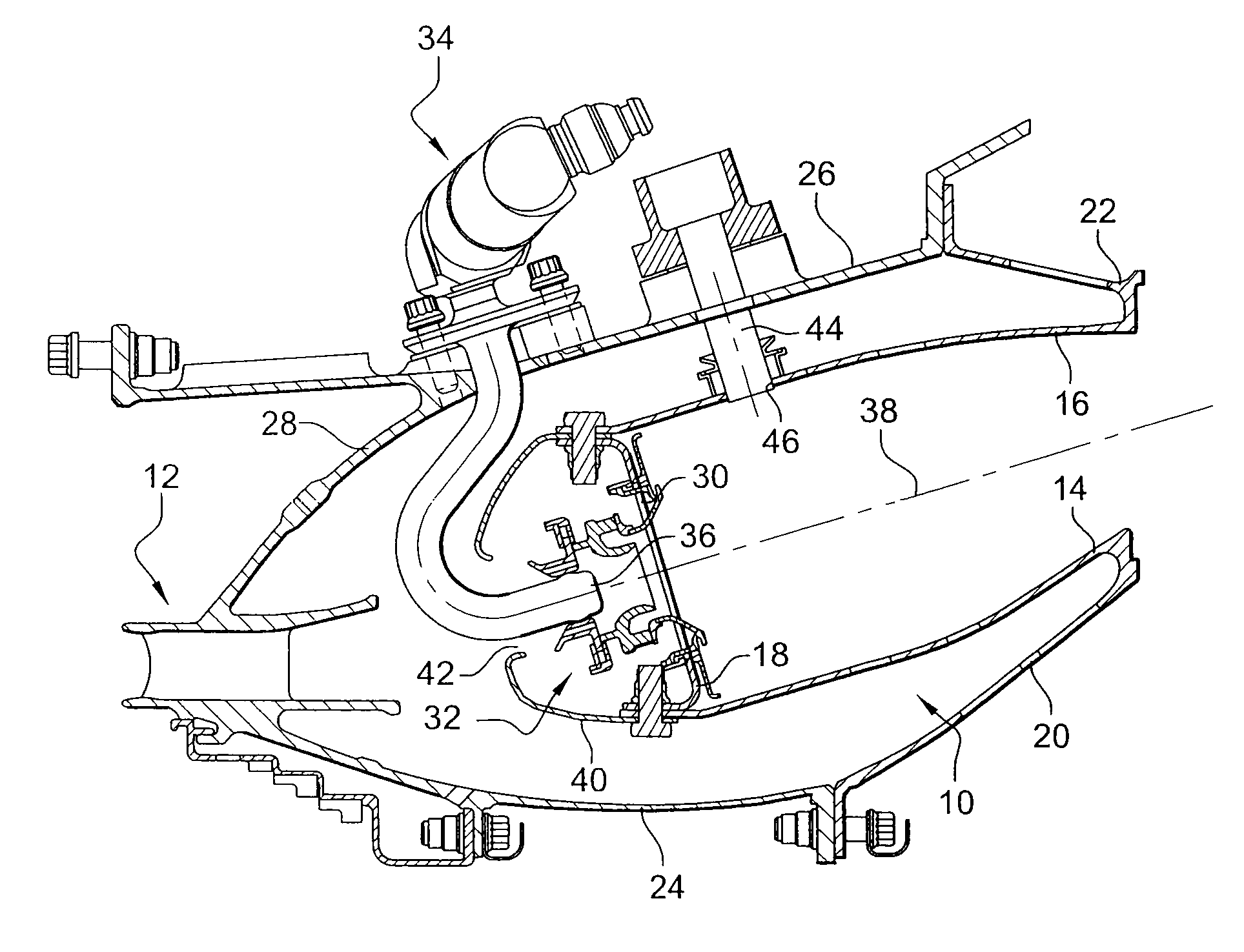
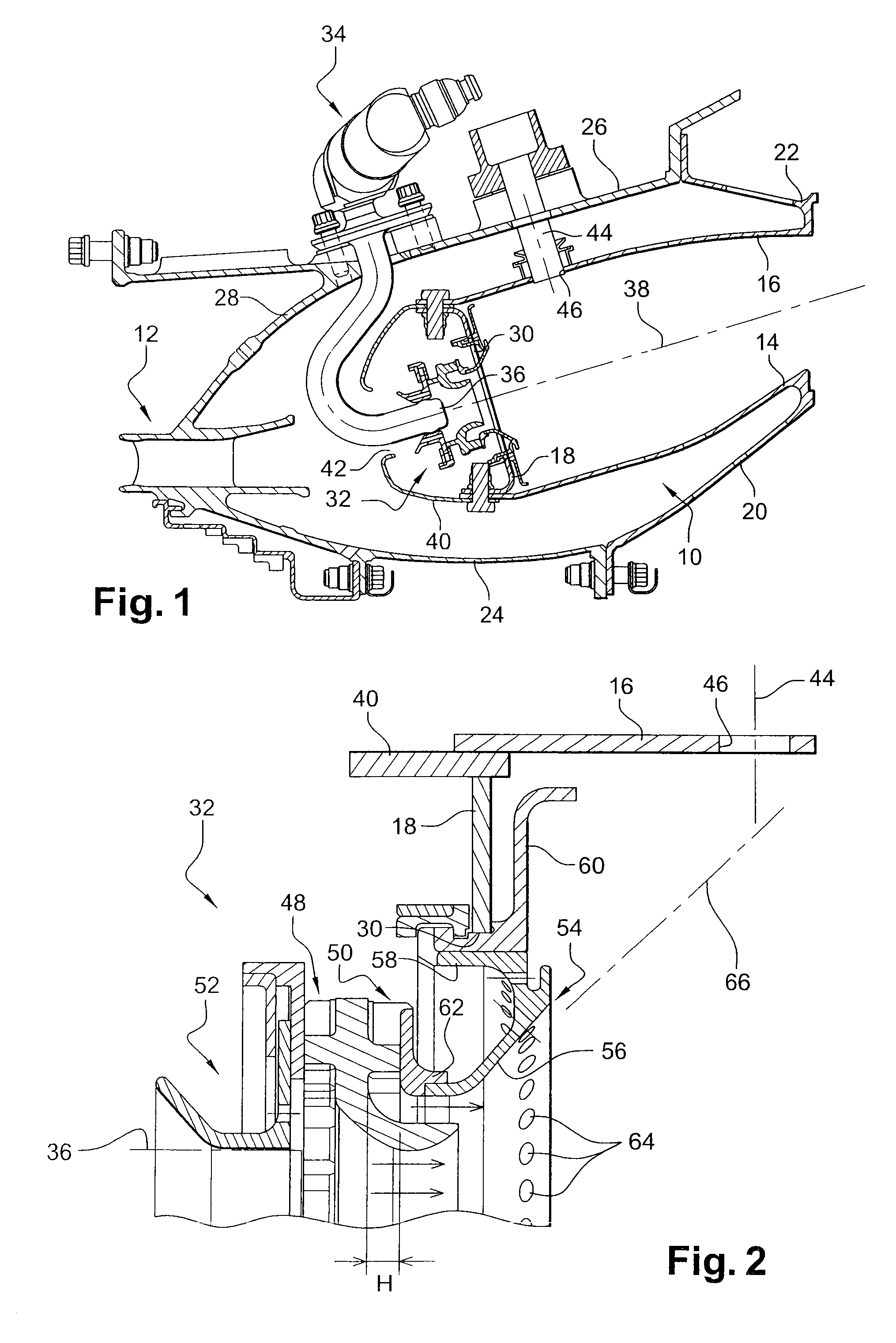
[0023]Reference is first made to FIG. 1 which shows an annular combustion chamber 10 for a turbomachine such as an aircraft turbojet or turboprop engine, arranged at the output of an annular diffuser 12, which is itself located at the output of a compressor (not shown).

[0024]The chamber 10 comprises an internal revolution wall 14 and an external revolution wall 16 connected upstream to a chamber base annular wall 18 and fixed downstream by respectively internal 20 and external 22 annular flanges on an internal tapered warp 24 of the diffuser, and on a downstream end of an external casing 26 of the chamber, the upstream end of this casing 26 being fixed on an external tapered warp 28 of the diffuser.

[0025]The chamber base wall 18 comprises openings 30 for mounting fuel injection systems 32 in the chamber 10, the air coming from the diffuser 12 and the fuel being supplied by injectors 34.

[0026]The injectors 34 are fixed at their radially external ends on the external casing 26 and reg...


PUM


Abstract

Turbomachine, comprising a combustion chamber provided with systems (132, 132′) for injecting fuel into the chamber, and with at least one spark plug (144), the injection system (132) located as close as possible to the spark plug being configured in order to produce a pool (166) of fuel having an angle of opening (β) of a greater value than that (α) of the pools (166′) produced by the other injection systems (132′), and having a flow of fuel greater than that of the other injection systems (132′).

Description

[0001]This invention relates to a turbomachine, such as an aircraft turbojet or turboprop engine, comprising an annular combustion chamber provided with at least one spark plug and fuel injection systems inside the chamber.BACKGROUND OF THE INVENTION[0002]A turbomachine annular combustion chamber comprises two coaxial revolution walls which extend one inside the other and which are connected together at their upstream ends by a chamber base annular wall, this chamber base wall comprising openings for mounting the aforementioned injection systems.[0003]The injection systems include supply ducts which extend substantially radially from an external casing of the chamber, and heads aligned axially with the openings of the chamber base wall. The head of each injector is provided with an atomizing nozzle producing a fuel cone in the chamber, this fuel cone being intended to mix with air coming from a compressor of the turbomachine in order to form a pool of air and fuel, substantially tap...

Claims


Application Information

Patent Timeline
Patent Type & Authority Applications(United States)
IPC IPC(8): F02C7/22F02C7/266
CPCF02C7/266F23R3/50F23R3/28
Inventor LAINS, DOMINIQUE MAURICE JACQUESSANDELIS, DENIS JEAN MAURICE
Owner SN DETUDE & DE CONSTR DE MOTEURS DAVIATION S N E C M A
Why Eureka
Try Eureka