Noise reducing poppet valve

a poppet valve and noise reduction technology, applied in the direction of lighting and heating apparatus, heating types, transportation and packaging, etc., can solve the problems of increasing air flow noise, annoying people near the conventional valve apparatus, increasing the amount, etc., to reduce the noise of the valve apparatus, reduce the drag, and reduce the effect of flow separation

Active Publication Date: 2010-09-16
THE BOEING CO
View PDF9 Cites 8 Cited by
  • Summary
  • Abstract
  • Description
  • Claims
  • Application Information

AI Technical Summary

Benefits of technology

[0005]In another embodiment, a personal valve apparatus may be provided. The personal valve apparatus may comprise a nozzle, a valve seat, a moveable poppet valve, and a stop cage. The nozzle may comprise a substantially straight inner air-flow surface having a nozzle cavity extending through the substantially straight inner air-flow surface. The valve seat may comprise a seat member disposed at an end of the substantially straight inner air-flow surface with the seat member disposed over the nozzle cavity. The moveable poppet valve may be disposed over the seat member and the nozzle cavity. The moveable poppet valve may comprise a convex surface which in an open position may be disposed over and apart from the seat member to allow air to flow from the nozzle cavity, against the convex surface, between the seat member and the convex surface, and beyond the seat member. In a closed position the convex surface may be disposed over and against the seat member to allow air flowing within the nozzle cavity to flow against the convex surface, and to substantially prevent air from flowing between the seat member and the convex surface, and beyond the seat member. The stop cage may be disposed over the moveable poppet valve, the seat member, and the nozzle cavity.
[0006]In an additional embodiment, a method of reducing noise in a valve apparatus is disclosed. In one step, a valve apparatus may be provided. The provided valve apparatus may comprise a nozzle, a valve seat, and a moveable poppet valve. The nozzle may comprise an inner air-flow surface having a nozzle cavity extending through the inner air-flow surface. The valve seat may comprise a seat member disposed at an end of the inner air-flow surface. The seat member may be disposed over the nozzle cavity. The moveable poppet valve may be disposed over the seat member and the nozzle cavity. The moveable poppet valve may comprise a convex surface. In another step, the moveable poppet valve may be opened by disposing the convex surface over and apart from the seat member to flow air from the nozzle cavity, against the convex surface, between the seat member and the convex surface, and beyond the seat member. In still another step, the moveable poppet valve may be closed by disposing the convex surface over and against the seat member to flow air within the nozzle cavity and against the convex surface, while substantially preventing air from flowing between the seat member and the convex surface, and beyond the seat member.
[0007]One or more embodiments of the disclosure may reduce one or more issues of one or more of the conventional valve apparatus and / or methods of flowing air within a conventional valve apparatus. For instance, one or more embodiments of the disclosure may decrease drag, may decrease flow separation, may decrease turbulence, and / or may decrease air flow noise within the valve apparatus. This may reduce noise-levels to humans near the valve apparatus. In other embodiments, additional types of problems of one or more conventional valve apparatus, and / or methods of flowing air within a conventional valve apparatus, may be reduced.

Problems solved by technology

Due to the shapes of the internal poppet valves and the curved nozzles, air flowing through conventional valve apparatus may experience an increased amount of drag, flow separation, and turbulence thereby leading to increased air flow noise.
This may be annoying to people near a conventional valve apparatus, such as to passengers in an aircraft utilizing a conventional valve apparatus as a personal air outlet with the passenger seat.

Method used


Image

  • Noise reducing poppet valve
  • Noise reducing poppet valve
  • Noise reducing poppet valve

Examples


Embodiment Construction

[0026]The following detailed description is of the best currently contemplated modes of carrying out the disclosure. The description is not to be taken in a limiting sense, but is made merely for the purpose of illustrating the general principles of the disclosure, since the scope of the disclosure is best defined by the appended claims.

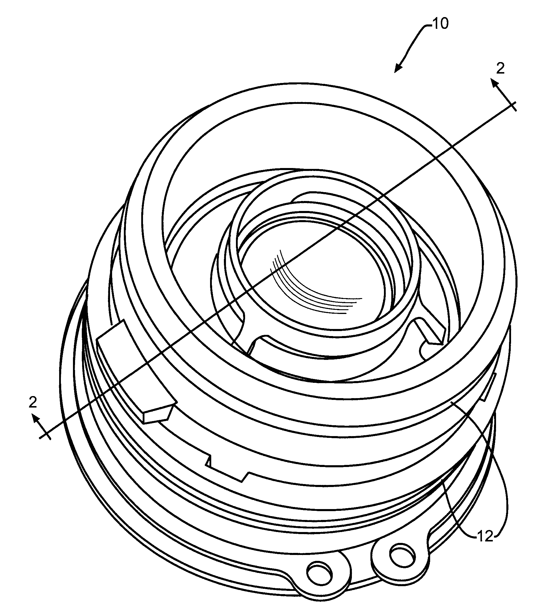
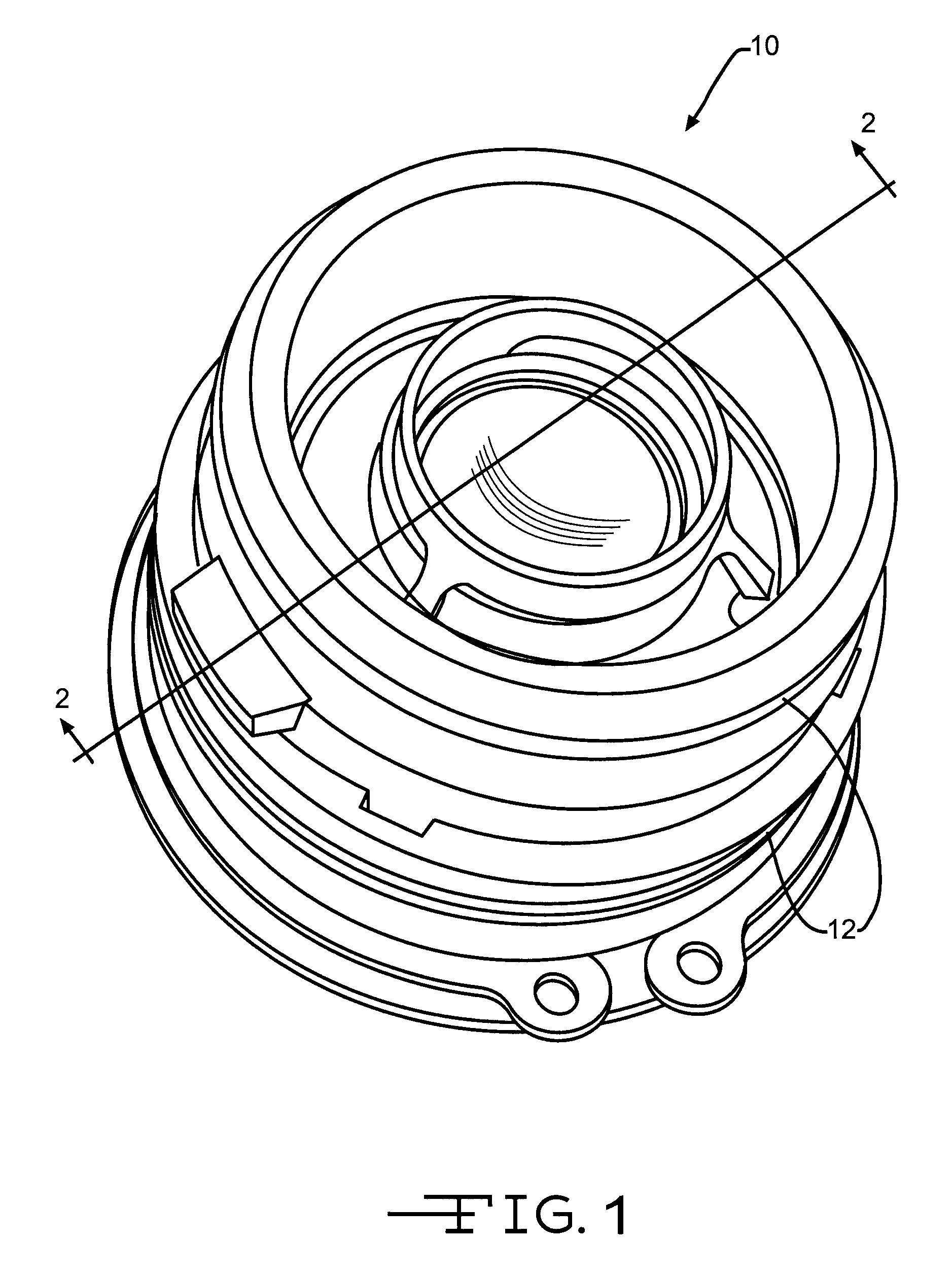
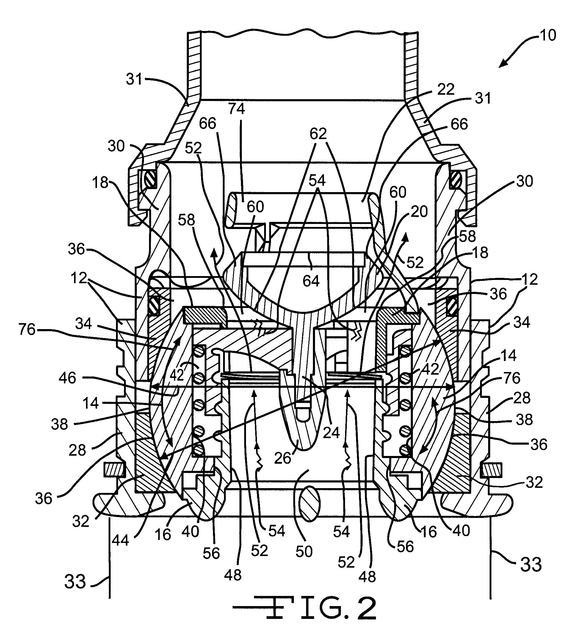
[0027]FIG. 1 is an illustration of a top perspective view of one embodiment of a valve apparatus 10. The valve apparatus 10 may comprise an airplane valve, a personal air outlet valve, and / or another type of valve apparatus. FIG. 2 is an illustration of a cross-section view through line 2-2 of the embodiment of FIG. 1. As shown in FIGS. 1-2, the valve apparatus 10 may include an outer housing 12, an inner housing 14, a nozzle 16, a valve seat 18, a moveable poppet valve 20, a stop cage 22, and first and second mating portions 24 and 26. The outer housing 12 may comprise a cylindrical bottom outer housing 28 coupled to a cylindrical upper outer housin...


PUM


Abstract

A personal valve apparatus may include a nozzle, a valve seat, and a moveable poppet valve. The nozzle may comprise an inner air-flow surface having a nozzle cavity extending through the inner air-flow surface. The valve seat may comprise a seat member disposed at an end of the inner-air-flow surface with the seat member disposed over the nozzle cavity. The moveable poppet valve may be disposed over the seat member and the nozzle cavity. The moveable poppet valve may comprise a convex surface. When the moveable poppet valve is in an open position, the convex surface may be disposed over and apart from the seat member to allow air to flow from the nozzle cavity, against the convex surface, between the seat member and the convex surface, and beyond the seat member. The convex surface of the poppet valve may reduce air turbulence, drag, flow separation, and/or noise within the valve apparatus.

Description

FIELD OF THE DISCLOSURE[0001]The field of the disclosure relates to noise reducing personal valve apparatus, such as aircraft personal air outlet valve apparatus, and to methods of reducing noise in such apparatus.BACKGROUND OF THE DISCLOSURE[0002]Conventional valve apparatus may utilize internal poppet valves which may be flat, may have relatively sharp corners and edges, and / or may have concave shapes. Other conventional valve apparatus may utilize curved nozzles. Due to the shapes of the internal poppet valves and the curved nozzles, air flowing through conventional valve apparatus may experience an increased amount of drag, flow separation, and turbulence thereby leading to increased air flow noise. This may be annoying to people near a conventional valve apparatus, such as to passengers in an aircraft utilizing a conventional valve apparatus as a personal air outlet with the passenger seat.[0003]An apparatus and method is needed which may solve one or more issues of one or more...

Claims


Application Information

Patent Timeline
Patent Type & Authority Applications(United States)
IPC IPC(8): F16K1/42
CPCB60H1/3442B60H2001/006F24F13/065B64D2013/003B64D13/00
Inventor JONES, RODERICK M.
Owner THE BOEING CO
Why Eureka
Try Eureka