
Vehicle airbag module

a technology for airbag modules and vehicles, applied in the field of maintaining the safety of riders, can solve the problems of increasing the material and labor costs of a finished airbag module, affecting the safety of passengers, so as to prevent the displacement of the cushion's neck

Inactive Publication Date: 2010-09-16
AUTOLIV ASP INC
View PDF8 Cites 14 Cited by
  • Summary
  • Abstract
  • Description
  • Claims
  • Application Information

AI Technical Summary

Benefits of technology

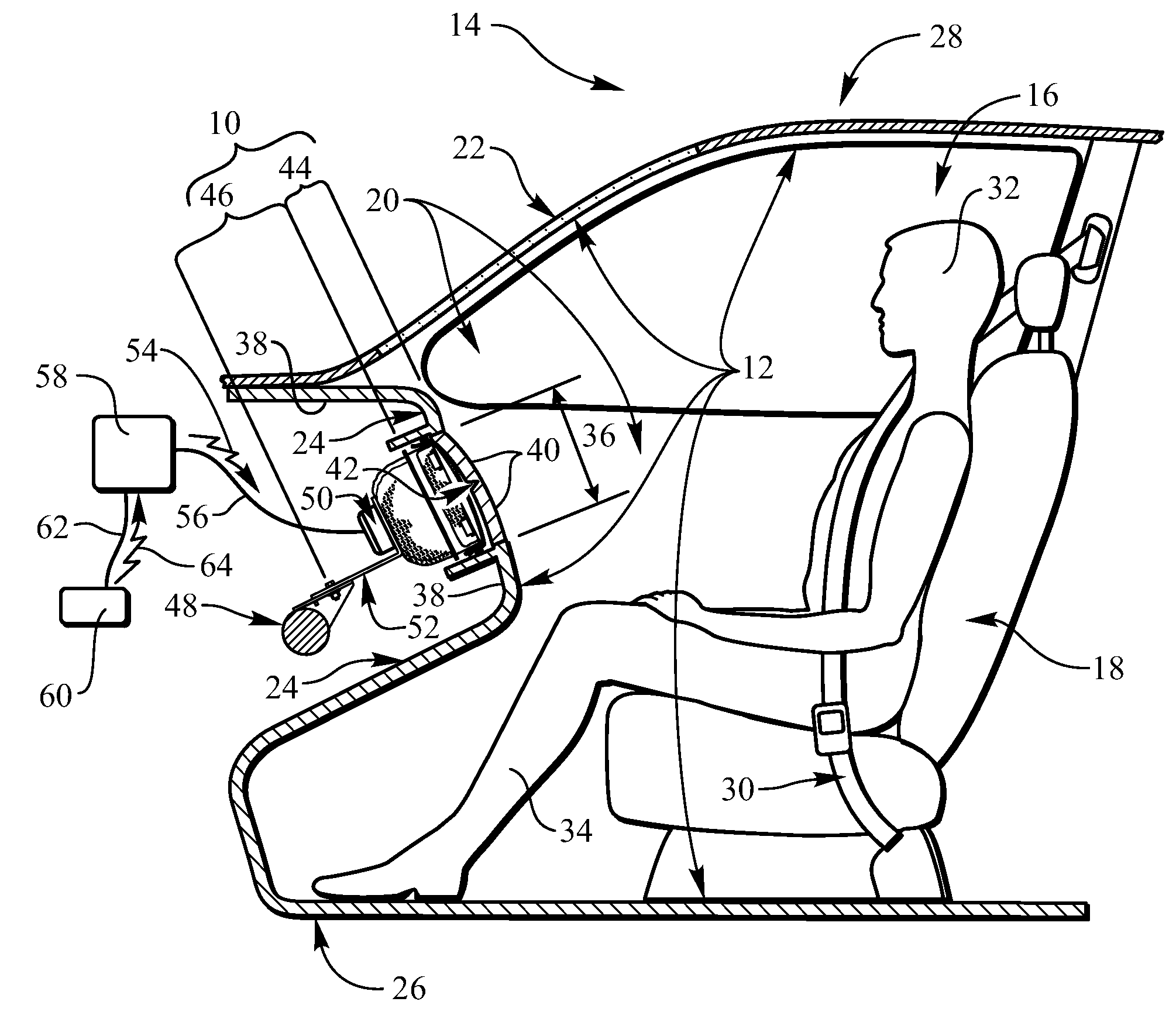
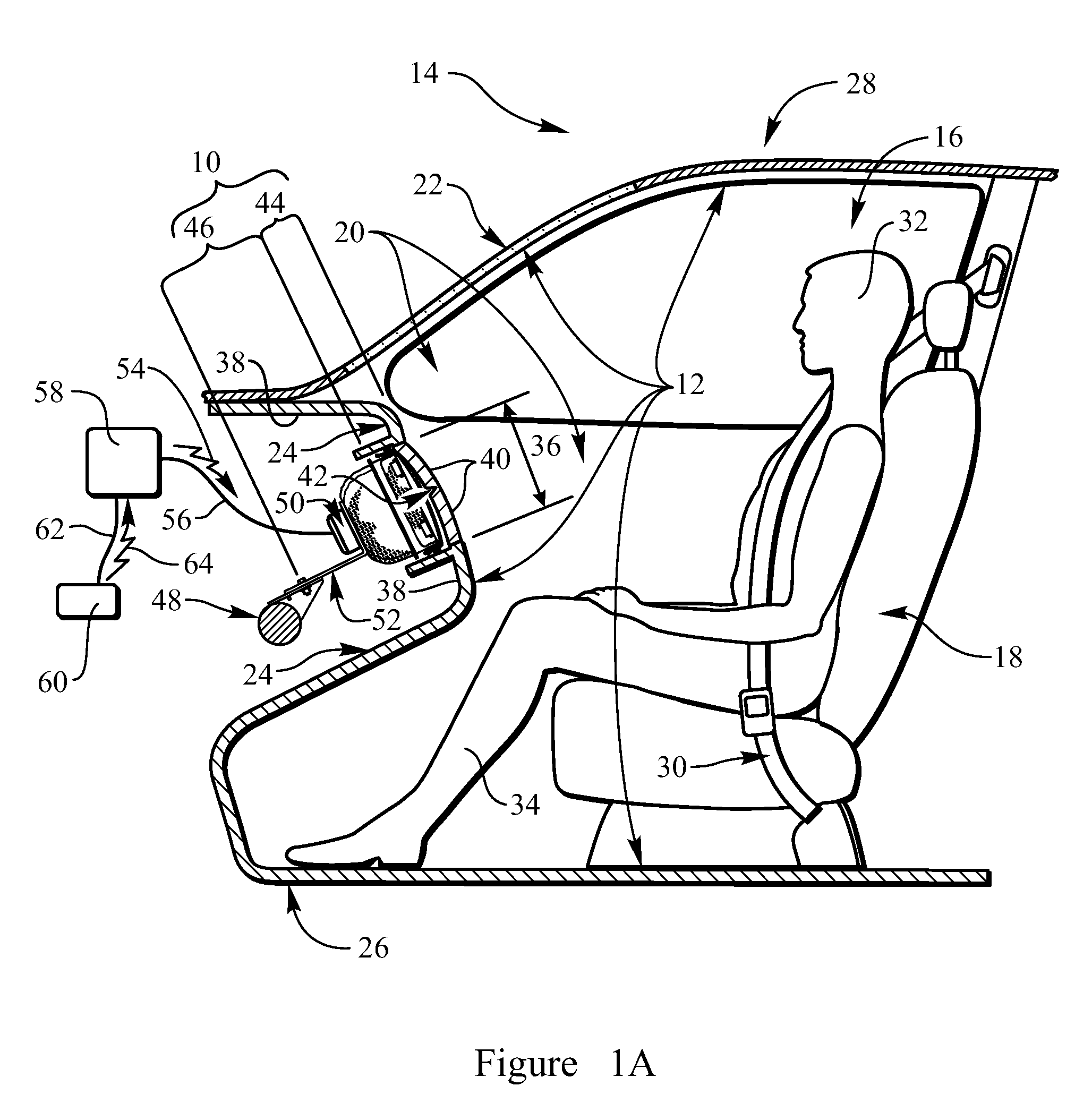
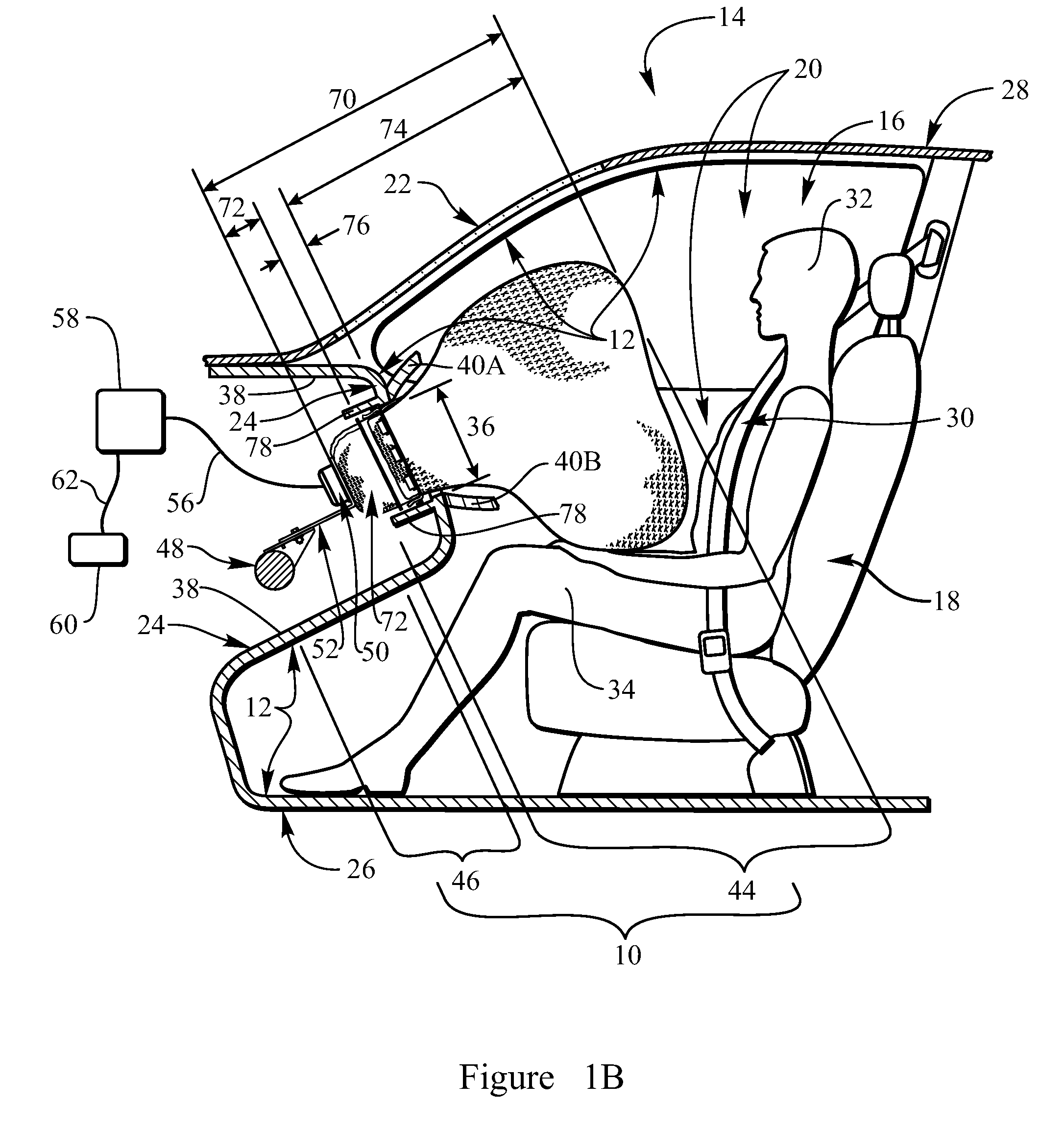
The present invention relates to an airbag module for protecting a rider in a vehicle from impacting the interior of the occupant enclosure in the event of a collision. The module includes an inflatable cushion and a rigid support collar for attachment to the occupant enclosure at an airbag deployment window. The cushion has an inflation portion, an activation portion, and a neck portion that interconnects the two portions in a fluid-tight communication. The support collar circumscribes the neck portion and has cushion hooks that prevent the cushion from displacing during inflation. The inflatable cushion also includes a flexible packaging cover with restraining apertures and cushion hooks that secure the cover to the support collar. The invention provides an improved airbag module that ensures the safety of riders in vehicles during collisions.

Problems solved by technology

Current airbag housings exhibit disadvantages, however.
An airbag housing is a complicated structure that adds significantly to the material and labor costs of a finished airbag module.
The inflator and the cushion are then each disposed in and attached to the housing procedures that are labor intensive and, therefore, relatively time consuming.
The housing itself is a heavy structure that contributes a significant fraction of the weight of a finished airbag module, detrimentally increasing the overall weight and decreasing the fuel consumption efficiency of the vehicle in which the airbag module is installed.

Method used


Image

  • Vehicle airbag module
  • Vehicle airbag module
  • Vehicle airbag module

Examples


Embodiment Construction

[0032]The present invention will be best understood by reference to the drawings, wherein like parts are designated by like numerals throughout. It should be understood that the components of the present invention, as generally described and illustrated in the figures herein, could be arranged and designed in a variety of different configurations. Thus, the following detailed description of an embodiment of the apparatus, system, and method of the present invention, as depicted in FIGS. 1A-7C, is not intended to limit the scope of the invention as claimed.

[0033]In this application, the phrases “connected to”, “coupled to”, and “in communication with” refer to any form of interaction between two or more entities, including mechanical, electrical, magnetic, electromagnetic, pneumatic, and thermal interactions.

[0034]The phrases “attached to”, “secured to”, and “mounted to” refer to a form of mechanical coupling that restricts relative translation or rotation between the attached, secur...


PUM


Abstract

An airbag module protects a rider in a vehicle from impacting the interior of the occupant enclosure of the vehicle. A rigid support collar is attached to the occupant enclosure proximate an airbag deployment window. An inflatable cushion has a neck portion that accommodates pressurized gas for driving the cushion through the deployment window into an inflated condition in the occupant enclosure. The cushion is attached by the neck portion directly to the support collar, while that substantial balance of the cushion is housed in a compact condition within the support collar. An attachment tab is secured to the exterior of the neck portion of the cushion with a restraining aperture formed therethrough. A cushion hook on the exterior of the support collar extends through the restraining aperture and prevents displacement of the neck portion of the cushion out of the support collar, when pressurized gas inflates the cushion. The cushion includes a flexible packaging cover having opposed first and second edges. The first edge is secured to the neck portion of the cushion, and the second edge is attached directly to support collar, while the packaging cover therebetween extends across the support collar retaining therein the cushion in the compact condition thereof.

Description

BACKGROUND OF THE INVENTION[0001]1. Field of the Invention[0002]The present invention pertains to maintaining the safety of riders in highway vehicles. More particularly, the present invention pertains to airbags for protecting a rider in a vehicle from impact with the interior of the occupant enclosure of the vehicle.[0003]2. Background of the Invention[0004]Inflatable safety restraint devices, or airbags, are now legally mandated in most new highway vehicles. Airbags are typically included at least in the steering wheel and in the dashboard on the passenger side of a highway vehicle. In addition, such airbags are occasionally installed to inflate beside a vehicle occupant and provide side impact protection, to inflate in front of the legs and protect the knees from forward impact, or to inflate at other strategic locations within the occupant enclosure of a highway vehicle.[0005]In the event of an accident, a sensor system within the vehicle detects an impact situation and trigger...

Claims


Application Information

Patent Timeline
Patent Type & Authority Applications(United States)
IPC IPC(8): B60R21/16
CPCB60R21/201B60R21/217B60R21/205
Inventor ROSE, LARRY D.LEWIS, ROBERTLEWIS, TRUDY
Owner AUTOLIV ASP INC
Learn More