Radar level gauge system with leakage detection

Inactive Publication Date: 2010-09-16
ROSEMOUNT TANK RADAR
View PDF6 Cites 23 Cited by
  • Summary
  • Abstract
  • Description
  • Claims
  • Application Information

AI Technical Summary

Benefits of technology

[0025]Furthermore, the plug may be arranged to move in a wave-guiding direction of the hollow waveguide when subjected to the force resulting from leakage of the fluid at the sealing member. In the case of a tubular hollow waveguide, this means that the plug may be arranged to move in the axial direction of the hollow waveguide. Hereby, a detectable change in microwave propagation characteristics of the hollow waveguide can be achieved rel

Problems solved by technology

In case of failure of the seal(s) of a radar level gauge system, there will be a l

Method used


Image

  • Radar level gauge system with leakage detection
  • Radar level gauge system with leakage detection
  • Radar level gauge system with leakage detection

Examples


Embodiment Construction

[0057]In the present description, embodiments of the present invention are mainly described with reference to a radar level gauge system in which the electromagnetic signals to be transmitted are provided from the transceiver to the antenna through an air-filled hollow waveguide with a circular cross-section. It should be noted that this by no means limits the scope of the present invention, which is equally applicable to a radar level gauge system having a hollow waveguide with another cross-section, such as rectangular, and / or having a hollow waveguide being at least partly filled with another dielectric medium and / or having more than one hollow waveguide for transmitting / receiving the electromagnetic signals.

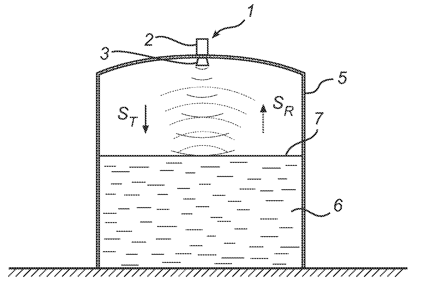
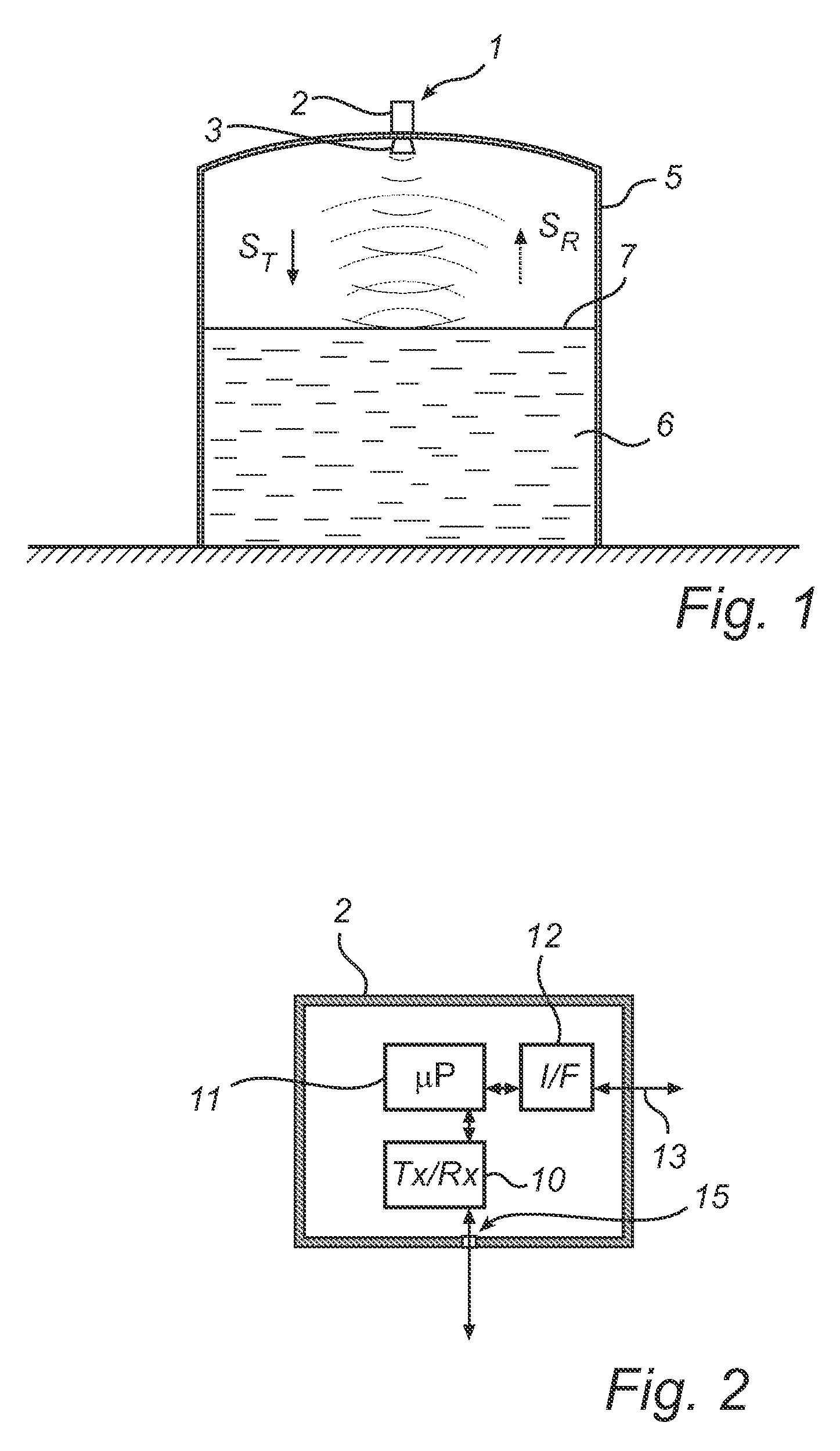
[0058]FIG. 1 schematically illustrates a radar level gauge system 1 according to an embodiment of the present invention, comprising a measurement electronics unit 2, and an antenna device 3. The radar level gauge system 1 is provided on a tank 5, which is partly filled with a...


PUM


Abstract

A radar level gauge system, for determining a filling level of a product contained in a tank, comprising a transceiver for generating, transmitting and receiving electromagnetic signals; an antenna arranged to direct transmitted electromagnetic signals towards a surface of the product contained in the tank, and to return reflected electromagnetic signals resulting from reflections at impedance transitions encountered by the transmitted electromagnetic signals back to the transceiver; and a hollow waveguide connecting the transceiver and the antenna for guiding the electromagnetic signals therebetween. A sealing member is arranged to seal the waveguide to prevent fluid from passing into the waveguide from an interior of the tank; and the radar level gauge system further comprises processing circuitry connected to the transceiver and configured to determine the filling level based on the reflected electromagnetic signals. The radar level gauge system further comprises a leak indication member being movably arranged inside the hollow waveguide in such a way that a force resulting from leakage of the fluid at the sealing member causes a movement of the leak indication member when acting thereon; and the hollow waveguide is configured in such a way that the movement of the leak indication member causes a change in at least one microwave propagation characteristic of the hollow waveguide.

Description

TECHNICAL FIELD OF THE INVENTION[0001]The present invention relates to a radar level gauge system for determining a filling level of a product contained in a tank and to a method for detecting leakage of fluid in a radar level gauge system.TECHNICAL BACKGROUND[0002]Radar level gauge systems are currently in use in a variety of fields of application for accurate filling level determination. For determining the filling level of a product by means of a radar level gauge system, electromagnetic signals are transmitted and propagated, usually by means of an antenna, towards a surface of the product, where signals are reflected. The reflected signals are received by the radar level gauge system, and the distance between a reference position and the surface of the product is determined by comparing the transmitted signals with the reflected signals. Based on this distance, the filling level can be determined.[0003]Most radar level gauge systems on the market today are either systems that d...

Claims


Application Information

Patent Timeline
IPC IPC(8): G01F23/284G01S13/08
CPCG01F25/0061G01F23/284G01F25/20
Inventor OHLSSON, MAGNUSROOS, CARL-JOHAN
Owner ROSEMOUNT TANK RADAR
Why Eureka
Try Eureka