Lane recognition device

a recognition device and lane technology, applied in the field oflane recognition devices, can solve problems such as inability, and achieve the effect of high reliability and shortening the period of lane marking detection

Active Publication Date: 2010-09-16
HONDA MOTOR CO LTD
View PDF7 Cites 52 Cited by
  • Summary
  • Abstract
  • Description
  • Claims
  • Application Information

AI Technical Summary

Benefits of technology

[0011]In view of such circumstances, an object of the present invention is to provide a lane recognition device which could shorten the period in which the recognition of the relative position of the lane mark and the vehicle is stopped, while securing high reliability of lane mark detection.

Problems solved by technology

Therefore, there is an inconvenience that it is not possible to promptly resume a lane maintaining control of assist driving a steering in order to maintain the traffic lane, or a departure warning control from the traffic lane and the like.

Method used


Image

  • Lane recognition device
  • Lane recognition device
  • Lane recognition device

Examples


first embodiment

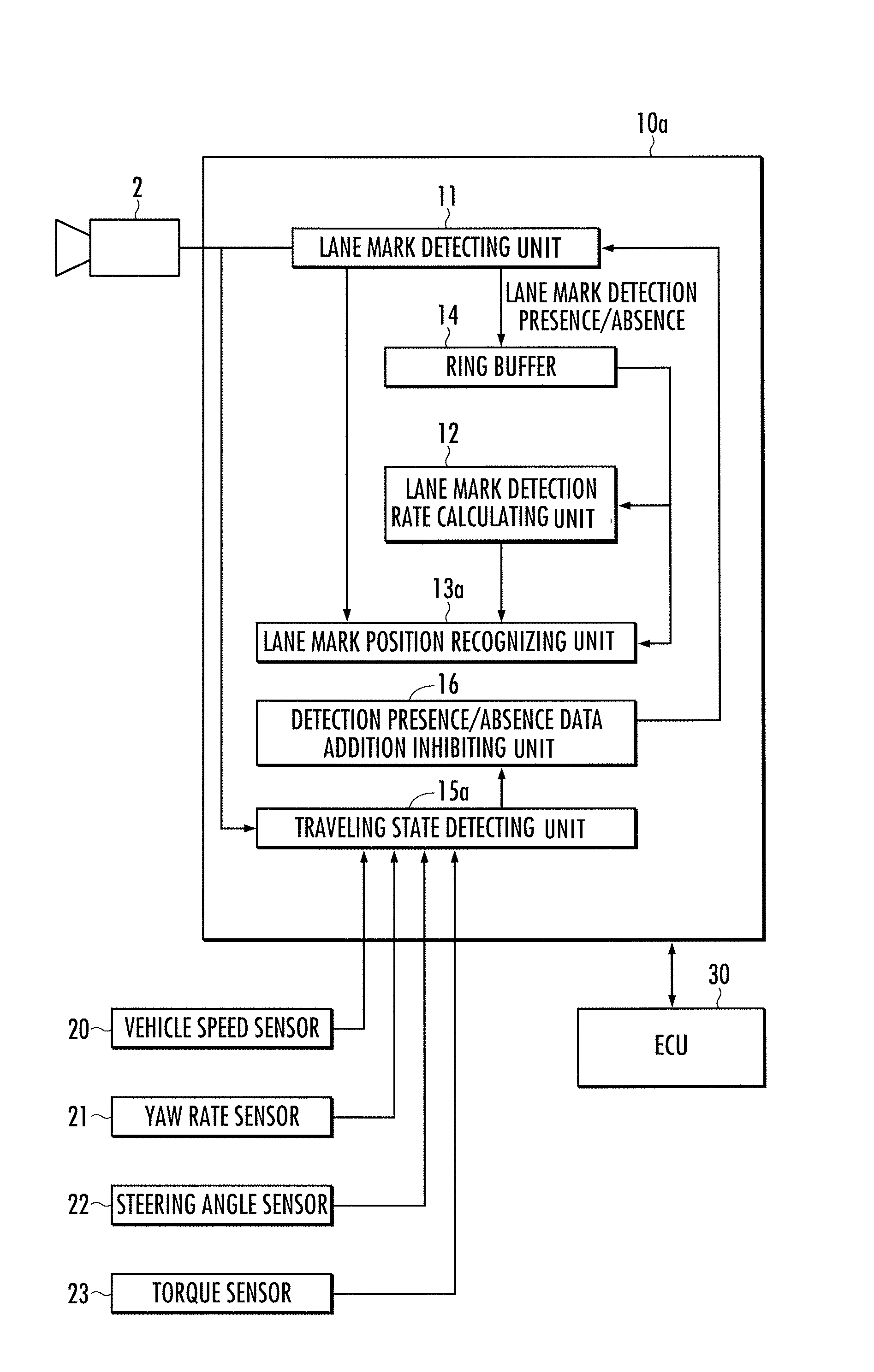
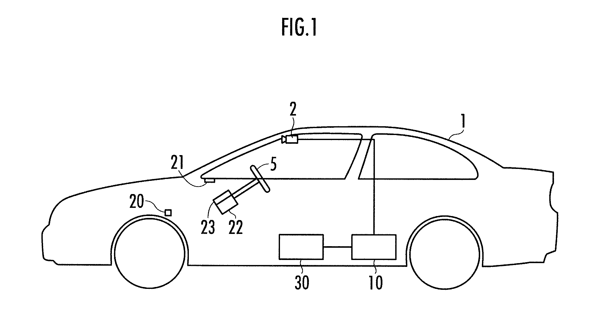
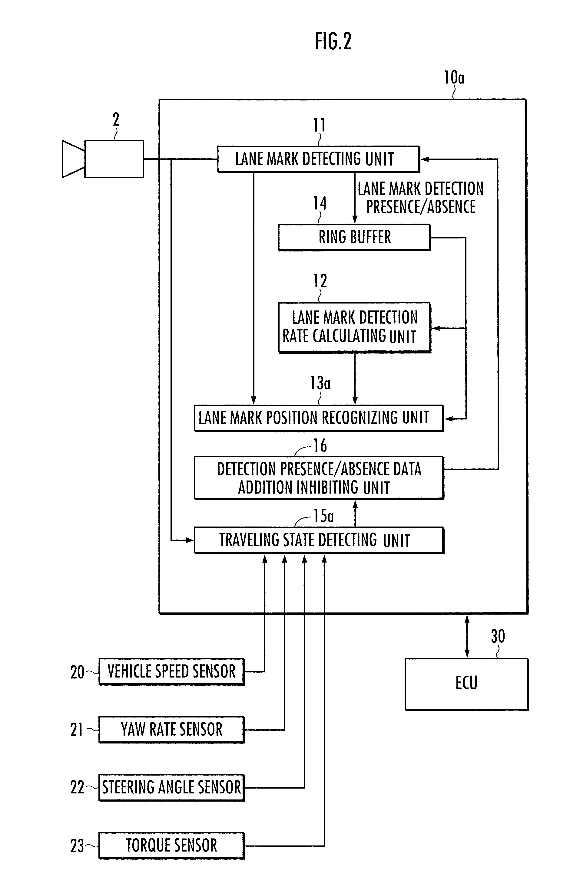
[0064]The first embodiment will now be explained with reference to FIG. 2 through FIG. 8. With reference to FIG. 2, the lane recognition device 10a is equipped with a lane mark detecting unit 11 which detects the lane mark (white lines, yellow lines, cat's eyes, Botts Dots and the like) from the image of the road in front of the vehicle which is captured by the camera 2 in each control cycle, a ring buffer 14 which is sequentially written with and which stores a detection presence / absence data showing the presence / absence of the lane mark detection by the lane mark detecting unit 11 (corresponds to a data storing unit of the present invention), a lane mark detection rate calculating unit 12 which calculates a lane mark detection rate which is an average detection rate of the lane mark from the detection presence / absence data stored in the ring buffer 14, a lane mark position recognizing unit 13a which recognizes the relative position of the vehicle and the lane mark, when the lane m...

second embodiment

[0095]A second embodiment of the invention will now be explained with reference to FIGS. 7A-7B, and 9 through 12. The configuration of the second embodiment is identical to the first embodiment, except that a part of the configuration of the lane recognition device 10b is different from that of the lane recognition device 10a of the first embodiment. The configuration which is the same as in the first embodiment is provided with the same reference number and the explanation thereof will be omitted.

[0096]With reference to FIG. 9, the lane recognition device 10b is equipped with a lane mark position recognizing unit 13b which recognizes the relative position of the vehicle and the lane mark, and a traveling state detecting unit 15b which detects that the vehicle 1 has passed through the intersection.

[0097]The lane recognition device 10b is an electronic unit configured from a microcomputer and the like, and the microcomputer functions as the lane mark detecting unit 11, the lane mark ...

first example

[0113]Next, explanation is given on a first example of the detecting process by the traveling state detecting unit 15b on the fact that the vehicle 1 has passed through the intersection. With reference to FIG. 11, the traveling state detecting unit 15b calculates a trajectory 60 of the vehicle 1 from t1, in which the lane mark detected state is switched to the lane mark undetected state (corresponds to the first point in time of the present invention), to t3, in which it is subsequently switched to the lane mark detected state (corresponds to the second point in time of the present invention).

[0114]More specifically, the traveling state detecting unit 15b calculates the trajectory 60 of the vehicle 1 from the traveling speed of the vehicle 1 detected by the vehicle speed sensor 20, and the yaw rate of the vehicle 1 detected by the yaw rate sensor 21. Thereafter, the traveling state detecting unit 15b detects that the vehicle 1 has passed through the intersection, when the conditions...


PUM


Abstract

The lane mark recognition device is equipped with a lane mark detecting unit which executes a lane mark detection process in each predetermined control cycle, and adds a detection presence / absence data to a ring buffer, a detection presence / absence data addition inhibiting unit which inhibits addition of the detection presence / absence data to the ring buffer when the vehicle is traveling in the intersection, and a lane mark position recognizing unit which recognizes a relative position of the vehicle and the lane mark, when the lane mark is detected in the situation where a lane mark detection rate calculated from the data of the ring buffer is higher than a reliability threshold value.

Description

BACKGROUND OF THE INVENTION[0001]1. Field of the Invention[0002]The present invention relates to a lane recognition device which recognizes a relative position of a vehicle and a lane mark, by detecting the lane mark partitioning a traffic lane of a road.[0003]2. Description of the Related Art[0004]Conventionally, there is proposed a technique of calculating a relative distance and the like of the lane mark and the vehicle, by obtaining a road image in each predetermined control cycle by a camera mounted on a vehicle, collecting candidates of image portion of the lane mark detected from each road image from a predetermined short period of time, and converting a camera coordinate of each image portion to a real space coordinate (for example, refer to Japanese Patent No. 3538476).[0005]In the conventional technique mentioned above, the real space position of the lane mark is recognized by collecting the candidates of the image portion of the lane mark detected from the road images obt...

Claims


Application Information

Patent Timeline
Patent Type & Authority Applications(United States)
IPC IPC(8): H04N7/18
CPCG06K9/00798G06V20/588
Inventor NAKAMORI, TAKUMAAOKI, TOMOYOSHITANAKA, JUNKOBAYASHI, SACHIO
Owner HONDA MOTOR CO LTD
Why Eureka
Try Eureka