Swirl generator, method for preventing flashback in a burner having at least one swirl generator and burner

Inactive Publication Date: 2010-09-23
SIEMENS AG
View PDF11 Cites 23 Cited by
  • Summary
  • Abstract
  • Description
  • Claims
  • Application Information

AI Technical Summary

Benefits of technology

[0005]An object of the present invention is to create an advantageous swirl generator and an advantageous burner compared with the cited prior art. A

Problems solved by technology

If too much fuel is now injected in proximity to the central distributor element, it may happen that this central region with low flow speed is supplied with too much fuel, which can result in flashback, which in the event of large loads is associated with very h

Method used


Image

  • Swirl generator, method for preventing flashback in a burner having at least one swirl generator and burner
  • Swirl generator, method for preventing flashback in a burner having at least one swirl generator and burner
  • Swirl generator, method for preventing flashback in a burner having at least one swirl generator and burner

Examples


Embodiment Construction

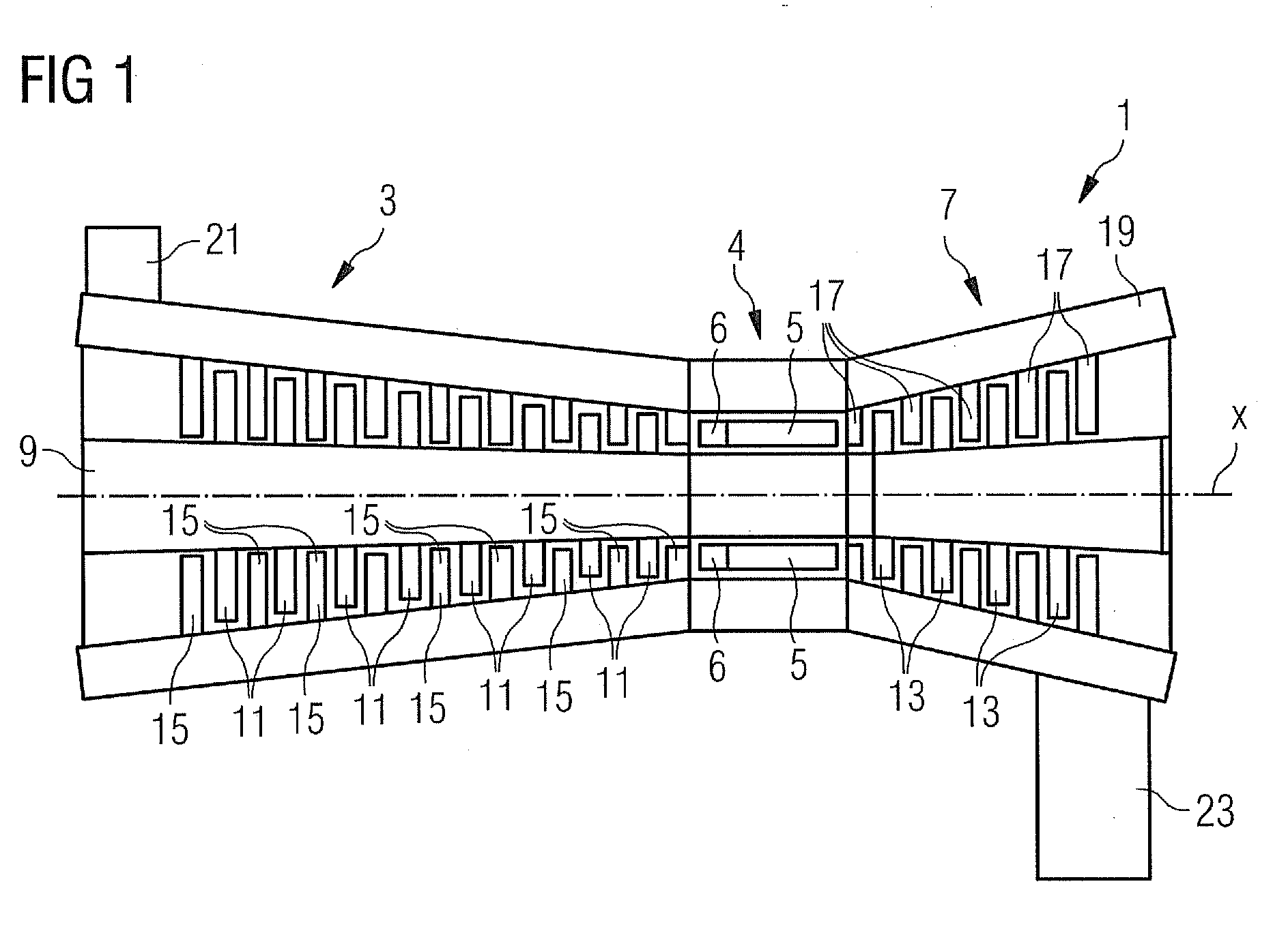
[0027]The structure and function of a gas turbine are described below with reference to FIG. 1, which shows a highly schematic sectional view of a gas turbine. The gas turbine 1 comprises a compressor segment 3, a combustion segment 4, which in the present exemplary embodiment comprises a number of tubular combustion chambers 5 with burners 6 disposed thereon, but in principle can also comprise an annular combustion chamber, and a turbine segment 7. A rotor 9 extends through all the segments and in the compressor segment 3 supports compressor blade rings 11 and in the turbine segment 7 supports turbine blade rings 13. Rings of compressor vanes 15 and rings of turbine vanes 17 are disposed between adjacent compressor blade rings 11 and between adjacent turbine blade rings 13, extending from a housing 19 of the gas turbine 1 radially outward in the direction of the rotor 9.

[0028]During operation of the gas turbine 1 air is drawn in through an air inlet 21 into the compressor segment 3...


PUM


Abstract

A swirl generator, a method for preventing flashback in a burner with a swirl generator and a burner are provided. The swirl generator includes a central fuel distributor element, an outer wall enclosing the central fuel distributor element and bounding an axial flow channel for combustion air, swirl vanes extending in a radial direction to the outer wall and giving the flowing combustion air a tangential flow component, and a separating wall enclosing the central fuel distributor element and being positioned radially within the outer wall. The separating wall divides the flow channel into a radially inner channel segment and a radially outer channel segment. The radially inner channel segment allows the combustion air to pass without giving it a tangential flow component or while giving it a tangential flow component counter to the orientation of the tangential flow component in the radially outer channel segment.

Description

CROSS REFERENCE TO RELATED APPLICATIONS[0001]This application claims priority of European Patent Office Application No. 09155904.7 EP filed Mar. 23, 2009, which is incorporated by reference herein in its entirety.FIELD OF INVENTION[0002]The present invention relates to a swirl generator having a central fuel distributor element and a burner having at least one swirl generator. The invention also relates to a method for preventing flashback in a burner, which comprises at least one swirl generator having a central fuel distributor element.BACKGROUND OF INVENTION[0003]Gas turbine burners having a central fuel distributor element and swirl generators enclosing the fuel distributor elements are described for example in DE 10 2007 004 394 A1, U.S. 2004 / 0055306 A1 and U.S. Pat. No. 6,082,111. In the burners described in US 2004 / 055306 A1 and U.S. Pat. No. 6,082,111 the swirl generator extends in each instance from the central fuel distributor element to a wall enclosing the central fuel d...

Claims


Application Information

Patent Timeline
IPC IPC(8): F02C7/22
CPCF23R3/286F23R3/14F23C7/004
Inventor HUTH, MICHAEL
Owner SIEMENS AG
Why Eureka
Try Eureka