Lighting Device

a technology of lighting devices and light bulbs, applied in the direction of fixed installations, lighting and heating devices, instruments, etc., can solve the problems of still being susceptible to improvement, and achieve the effect of reducing the degradation of the lighting devi

Active Publication Date: 2010-09-23
SEMICON ENERGY LAB CO LTD
View PDF37 Cites 20 Cited by
  • Summary
  • Abstract
  • Description
  • Claims
  • Application Information

AI Technical Summary

Benefits of technology

[0013]According to one embodiment of the present invention, a lighting device in which the luminance of an EL element is maintained regardless of degradation of the EL element so that degradation of the lighting device is reduced can be provided.

Problems solved by technology

Accordingly, although a lighting device including an EL element is a very promising lighting device as a surface light source, it is still susceptible of improvement.

Method used


Image

  • Lighting Device
  • Lighting Device
  • Lighting Device

Examples


embodiment 1

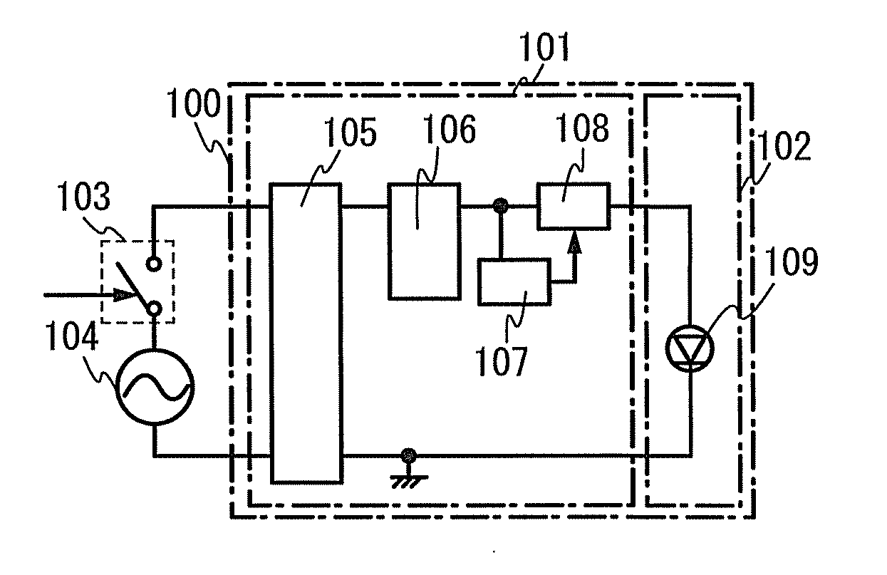
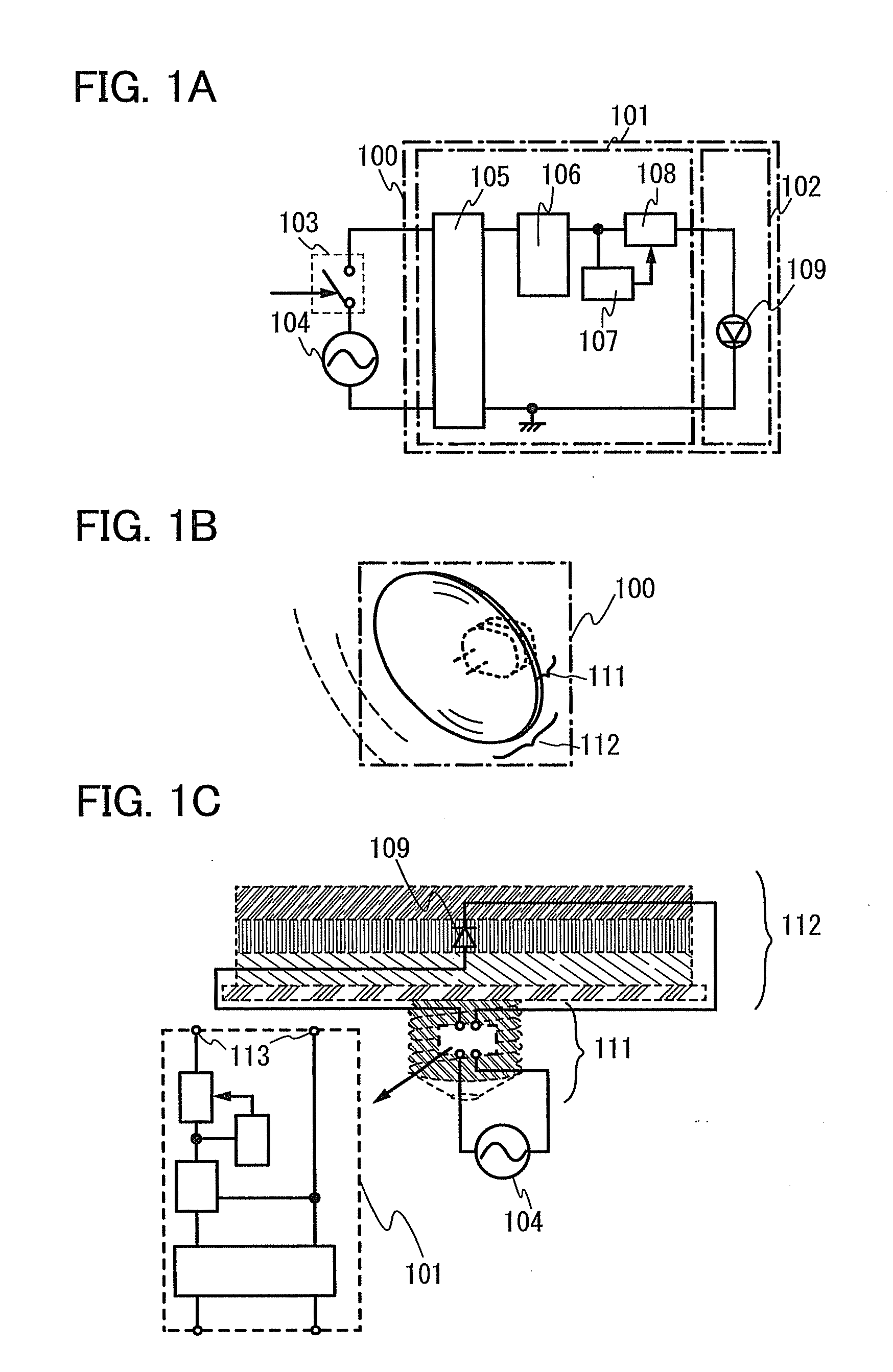
[0035]FIG. 1A illustrates a structure of a block diagram of a lighting device. A lighting device 100 illustrated in FIG. 1A includes a control circuit portion 101 and a surface light source portion 102. A power supply voltage is supplied from an alternating-current power supply 104 to the control circuit portion 101 through a lighting switch 103. The control circuit portion 101 includes a rectifier and smoothing circuit 105, a constant voltage circuit 106 (also referred to as a stabilization circuit), a luminance adjustment circuit 107, and a variable current source circuit 108. Moreover, the surface light source portion 102 includes a light-emitting element 109.

[0036]In the lighting device 100 in FIG. 1A, an alternating-current voltage output from a power supply (an alternating-current power supply) is made to pulsate by the rectifier and smoothing circuit 105 in the control circuit portion 101, and a direct-current voltage with ripples (also referred to as a pulsating direct-curre...

embodiment 2

[0071]In this embodiment, an example of the round-shaped light source portion which is described in Embodiment 1 will be described with reference to drawings.

[0072]As an example, in a round-shaped light source portion shown in this embodiment, a first electrode, an organic EL layer, and a second electrode are stacked over a substrate having an opening portion at the center, and the center of the substrate has a first connection portion and a second connection portion.

[0073]A specific structure will be described below with reference to FIG. 9 and FIGS. 10A and 10B. FIG. 9 is a plan schematic diagram of a round-shaped light source portion. FIG. 10A is a schematic diagram of a cross section along A-B in FIG. 9. FIG. 10B is a schematic diagram of a cross section along C-D in FIG. 9.

[0074]A round-shaped light source portion 930 illustrated in FIG. 9 and FIGS. 10A and 10B has an opening portion 909 at the center and includes a round-shaped substrate 901, a light-emitting element 932 provi...

embodiment 3

[0109]In this embodiment, another example of a round-shaped light source portion, which is different from that in Embodiment 2, will be described with reference to FIG. 16 and FIGS. 17A and 17B.

[0110]FIG. 16 is a plan view of a round-shaped light source portion. FIG. 17A is a cross-sectional view along E-F in FIG. 16. FIG. 17B is a cross-sectional view along G-H in FIG. 16.

[0111]The light-emitting element 932 including the first electrode 904, the organic EL layer 906, and the second electrode 908 is formed over the substrate 901 where the insulating film 902 is provided as a base protective film (a barrier layer). The light-emitting element 932 except parts of the first electrode 904 and the second electrode 908 is covered with the insulating film 910. The insulating film 910 functions as a protective layer (a sealing film) for protecting the organic EL layer 906 in the light-emitting element 932 from contaminants such as moisture from the outside. Note that the substrate 901 has a...


PUM


Abstract

To provide a lighting device in which the luminance of an EL element is maintained even when the EL element deteriorates so that degradation of the lighting device is reduced, the lighting device includes a surface light source portion including an organic EL element, and a control circuit portion provided in a base portion. The control circuit portion counts a lighting time of the organic EL element and controls the luminance of the organic EL element in accordance with the lighting time. Accordingly, the lighting device in which the luminance of an EL element is maintained regardless of degradation of the EL element so that degradation of the lighting device is reduced can be provided.

Description

TECHNICAL FIELD[0001]The present invention relates to a lighting device. The present invention particularly relates to a lighting device using a light-emitting element which includes a layer containing a light-emitting substance with which electroluminescence (hereinafter referred to as EL) can be obtained.BACKGROUND ART[0002]Since awareness of environmental problems has been raised, lighting devices including LEDs instead of incandescent lamps have been actively developed and commercialized. Moreover, in recent years, a lighting device using an organic EL element (hereinafter referred to as an EL element) which is a surface light source has also been developed (e.g., see Patent Document 1).REFERENCE[0003]Patent Document 1: Japanese Published Patent Application No. 2007-227523DISCLOSURE OF INVENTION[0004]Luminance characteristics of an EL element are changed as lighting time accumulated (referred to as accumulated lighting time) is increased. In other words, when current is supplied...

Claims


Application Information

Patent Timeline
Patent Type & Authority Applications(United States)
IPC IPC(8): H05B37/02H05B33/08H05B44/00
CPCH05B33/0896F21K9/13F21S6/00H05B33/08F21S8/04F21Y2105/006F21S8/033F21Y2105/00F21K9/23F21Y2115/20H05B45/60Y02B20/30H05B44/00F21K9/20
Inventor YAMAZAKI, SHUNPEIKOYAMA, JUN
Owner SEMICON ENERGY LAB CO LTD
Why Eureka
Try Eureka