Optical touch screen systems using reflected light

a technology of optical touch screen and reflected light, applied in the field of light-based touch screen, can solve the problems of insufficient versatility of systems to offer an all-encompassing solution, power consumption, screen not fully transparent, etc., and achieve the effect of low cost, selective area touch, and touch screen cos

Inactive Publication Date: 2010-09-23
NEONODE
View PDF102 Cites 147 Cited by
  • Summary
  • Abstract
  • Description
  • Claims
  • Application Information

AI Technical Summary

Benefits of technology

[0023]The present invention is of particular advantage in providing low cost touch screens with selective area touch. Conventional capacitive and resistive touch screens are costly, since the required screen overlay generally cannot be used to cover only a sub-area of the screen surface. Furthermore, the wiring used in conventional capacitive and resistive touch screens generally traverses the entire screen. As such, for large screens the wires must be long and thick.
[0024]In distinction, the present invention is scalable, and the cost of the touch screen is generally proportional to the perimeter of the touch sensitive sub-area.

Problems solved by technology

Such systems are not versatile enough to offer an all encompassing solution, as they are not easily scalable.
Advantages of resistive touch screens are their low cost, low power consumption and stylus support.
A disadvantage of resistive touch screens is that as a result of the overlay, the screens are not fully transparent.
Another disadvantage is that the screens require periodic re-calibration.
Another disadvantage is that pressure is required for touch detection; i.e., a pointer that touches the screen without sufficient pressure goes undetected.
As a consequence, resistive touch screens do not work well with fingers.
Another disadvantage is that resistive touch screens are generally unreadable in direct sunlight.
Another disadvantage is that resistive touch screens are sensitive to scratches.
Yet another disadvantage is that resistive touch screens are unable to discern that two or more pointers are touching the screen simultaneously, referred to as “multi-touch”.
A disadvantage of surface capacitive touch screens is that as a result of the overlay, the screens are not fully transparent.
Another disadvantage is a limited temperature range for operation.
Another disadvantage is a limited capture speed of pointer movements, due to the capacitive nature of the touch screens.
Another disadvantage is that surface capacitive touch screens are susceptible to radio frequency (RF) interference and electromagnetic (EM) interference.
Another disadvantage is that the accuracy of touch location determination depends on the capacitance.
Another disadvantage is that surface capacitive touch screens cannot be used with gloves.
Another disadvantage is that surface capacitive touch screens require periodic re-calibration.
Another disadvantage is that surface capacitive touch screens require a large screen border.
As a consequence, surface capacitive touch screens cannot be used with small screen devices.
Yet another disadvantage is that surface capacitive touch screens are unable to discern a mufti-touch.
A disadvantage of projective capacitive touch screens is that as a result of the overlay, the screens are not fully transparent.
Another disadvantage is their high cost.
Another disadvantage is a limited temperature range for operation.
Another disadvantage is a limited capture speed, due to the capacitive nature of the touch screens.
Another disadvantage is a limited screen size, typically less than 5″.
Another disadvantage is that surface capacitive touch screens are susceptible to RF interference and EM interference.
Yet another disadvantage is that the accuracy of touch location determination depends on the capacitance.
It will thus be appreciated that conventional touch screens are impractical for general use with small mobile devices and devices with large screens.

Method used


Image

  • Optical touch screen systems using reflected light
  • Optical touch screen systems using reflected light
  • Optical touch screen systems using reflected light

Examples


Embodiment Construction

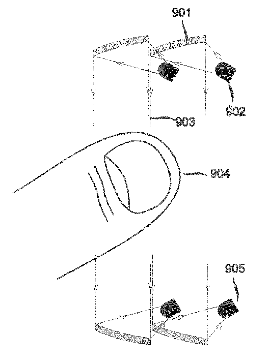
[0119]Aspects of the present invention relate to light-based touch screens and light-based touch surfaces. According to embodiments of the present invention, a light-based touch screen includes one or more infra-red or near infra-red light-emitting diodes (LEDs) and a plurality of photodiodes (PDs) arranged along the perimeter surrounding the touch screen or touch surface. The LEDs project light substantially parallel to the screen surface, and this light is detected by the PDs. A pointer, such as a finger or a stylus, placed over a portion of the screen blocks some of the light beams, and correspondingly some of the PDs detect less light intensity. The geometry of the locations of the PDs, and the light intensities they detect, suffice to determine screen coordinates of the pointer. The LEDs and PDs are controlled for selective activation and de-activation by a controller. Generally, each LED and PD has I / O connectors, and signals are transmitted to specify which LEDs and which PDs...


PUM


Abstract

A touch screen system, including a near-infrared transparent screen including a plurality of reflective elements embedded therein, a circuit board including circuitry for controlled selective activation of electronic components connected thereto, at least one light source connected to the circuit board, for emitting light, and at least one light detector connected to the circuit board, for detecting light emitted by the at least one light source and reflected by the reflective elements.

Description

CROSS REFERENCES TO RELATED APPLICATIONS[0001]This application claims benefit of U.S. Provisional Application No. 61 / 169,779, entitled OPTICAL TOUCH SCREEN, filed on Apr. 16, 2009 by inventors Magnus Goertz, Thomas Eriksson and Joseph Shain, the contents of which are hereby incorporated by reference.[0002]This application also claims benefit of U.S. Provisional Application No. 61 / 171,464, entitled TOUCH SCREEN USER INTERFACE, filed on Apr. 22, 2009 by inventor Magnus Goertz, the contents of which are hereby incorporated by reference.[0003]This application is also a continuation-in-part of pending U.S. application Ser. No. 12 / 371,609 entitled LIGHT-BASED TOUCH SCREEN, filed on Feb. 15, 2009 by inventors Magnus Goertz, Thomas Eriksson and Joseph Shain.FIELD OF THE INVENTION[0004]The field of the present invention is light-based touch screens.BACKGROUND OF THE INVENTION[0005]Many consumer electronic devices are now being built with touch sensitive screens, for use with finger or stylus...

Claims


Application Information

Patent Timeline
Patent Type & Authority Applications(United States)
IPC IPC(8): G06F3/042
CPCG06F3/042G06F3/0428G06F3/0425G06F3/0421
Inventor GOERTZ, MAGNUSERIKSSON, THOMASSHAIN, JOSEPH
Owner NEONODE
Why Eureka
Try Eureka