
Developing apparatus and image forming apparatus

Active Publication Date: 2010-09-23
KONICA MINOLTA BUSINESS TECH INC
View PDF6 Cites 9 Cited by
  • Summary
  • Abstract
  • Description
  • Claims
  • Application Information

AI Technical Summary

Benefits of technology

[0011]Accordingly, an object of the present invention is to provide a developing apparatus and an image forming apparatus which can appropriately regulate a discharge amount of a developer.
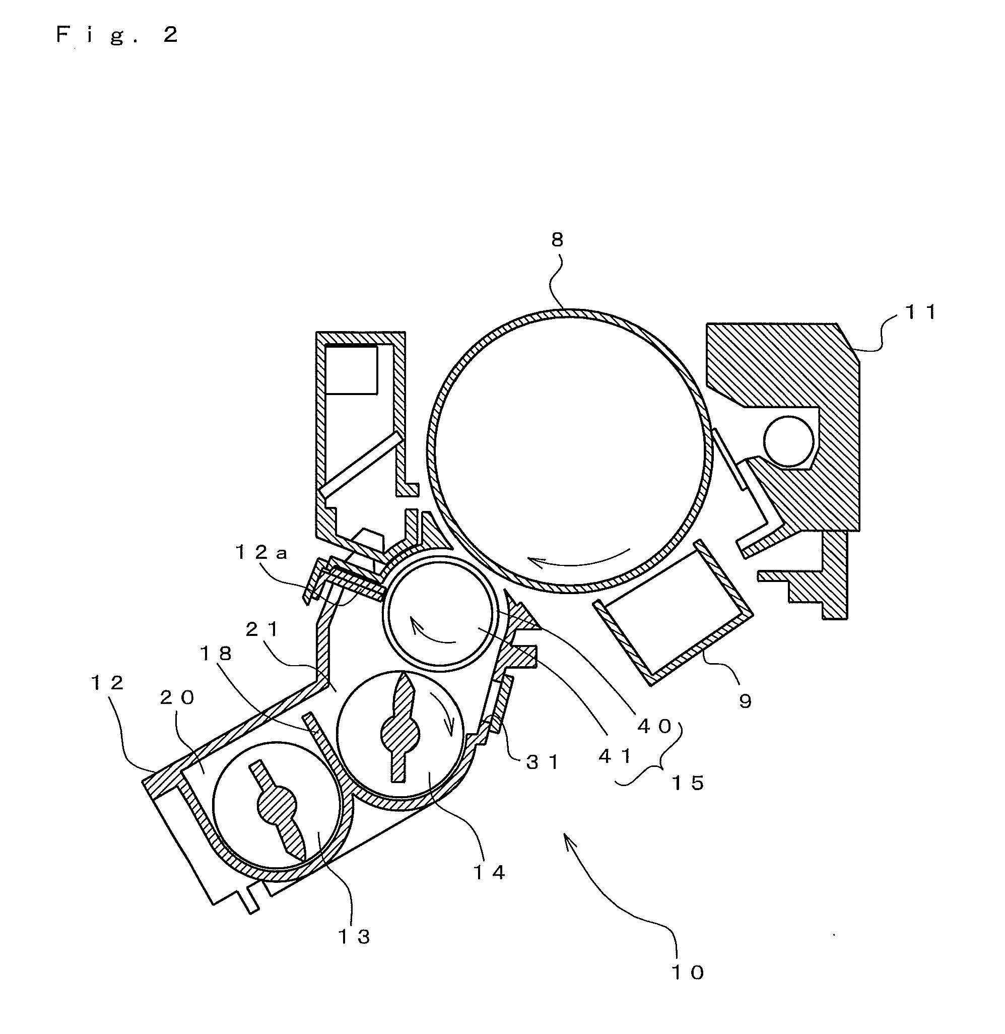
[0025]In accordance with this structure, it is possible to stabilize the liquid surface position by regulating the amount of the developer heading for the developer discharge portion by the flow rate regulating portion. Accordingly, in comparison with the case that the discharge amount of the developer is regulated directly by the developer discharge portion, it is possible to appropriately regulate the discharge amount of the developer.
[0031]In accordance with this structure, it is possible to set the amount of the developer discharged via the developer discharge portion to a more appropriate value. In other words, in the case that the presumed weight of the developer goes beyond the previously set reference value, it is possible to rapidly regulate the weight of the developer circulating within the developer accommodating container to the reference value by increasing the amount of the developer which is put through by the flow rate regulating portion. Further, in the case that the presumed weight of the developer is less than the previously set reference value, it is possible to suppress the amount of the developer discharged via the developer discharge portion, by reducing the amount of the developer which can pass through by the flow rate regulating portion.
[0039]In accordance with the present invention, it is possible to regulate the passing amount of the developer in the stage before running into the developer discharge portion by the flow rate regulating portion. Accordingly, it is possible to securely set the discharge amount of the developer in the developer discharge portion to the desired value.

Problems solved by technology

However, in any developing apparatus mentioned above, it is hard to set a discharge amount of the developer to an appropriate value.
In other words, in the developing apparatus described in the Japanese Patent No. 3014563, it is only possible to prevent the developer from running into the discharge opening all at once by the protruding portion.
Since it is necessary not only to suppress the discharge amount of the developer, but also to promote it, it is impossible to obtain an appropriate discharge amount only by suppressing by means of the protruding portion.
A liquid surface of the developer is displaced in accordance with a position within the developing apparatus, on the basis of a variation of an inclination of the developing apparatus and a system speed (a rotating speed of a photoreceptor, a sheet feeding speed or the like), however, it is impossible to sufficiently correspond to the displacement of the liquid surface only by opening and closing the discharge opening.
In other words, it is impossible to appropriately regulate a discharge amount of the developer.

Method used


Image

  • Developing apparatus and image forming apparatus
  • Developing apparatus and image forming apparatus
  • Developing apparatus and image forming apparatus

Examples


second embodiment

3-1. Second Embodiment

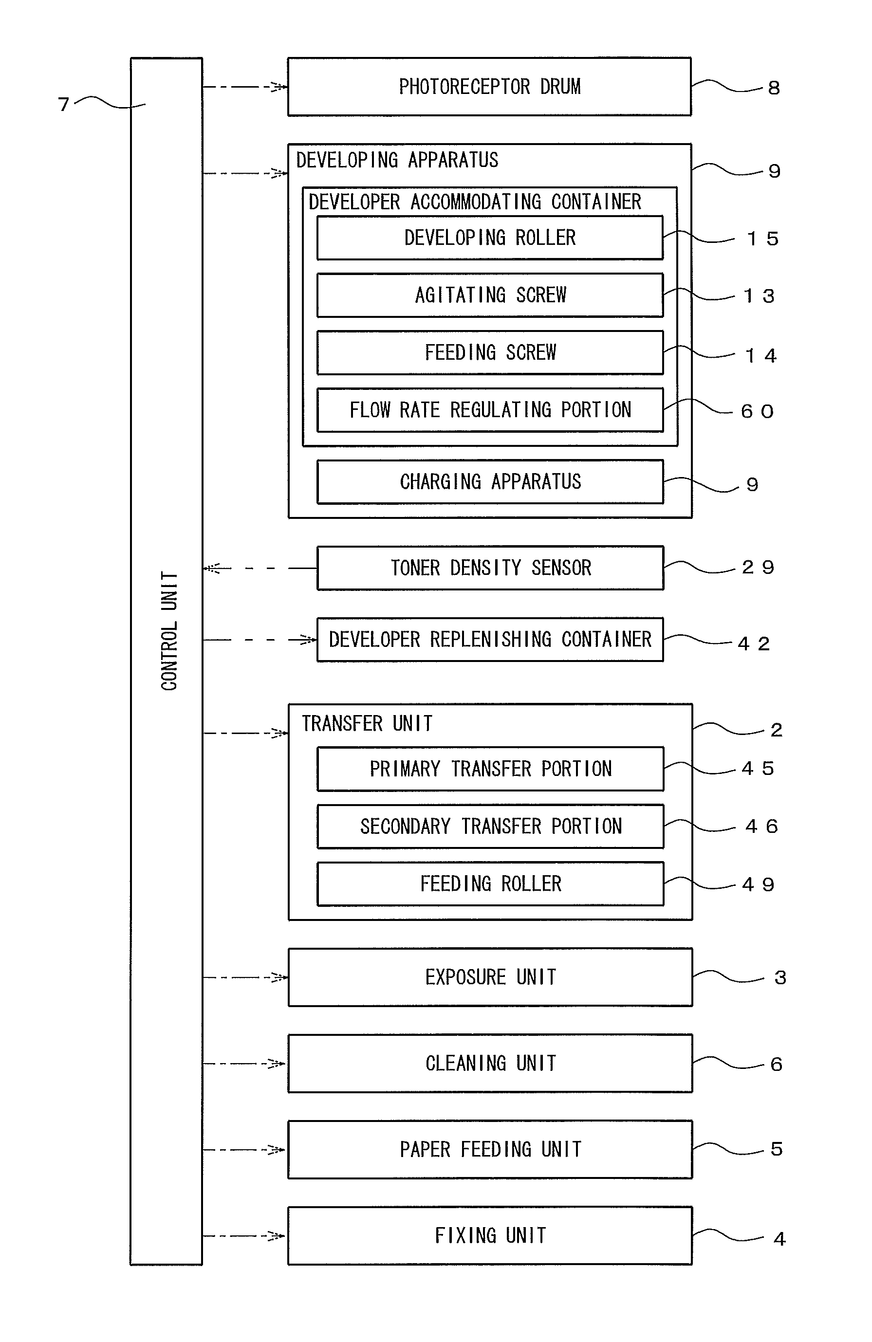
[0089]FIG. 6 is structured such that an inner diameter of the opening portion 61 is enlarged or contracted by constructing the flow rate regulating portion 60 by a plurality of diaphragm blades 65 which may be used for a diaphragm for a lens.

[0090]In accordance with this structure, it is possible to freely regulate the opening area by the diaphragm blade 65. Accordingly, it is possible to accurately control in comparison with the case that the substantial opening area is regulated by the magnetization. Further, it is possible to correspond not only to the case that the toner amount of consumption is extremely large and it is necessary to suppress the discharge amount of the developer, but also to the case that the carrier is deteriorated and the charging capacity is lowered.

[0091]For example, in the case that the opening area is set to a changeable medium value at a normal time, and a great amount of images having a high BW ratio are printed, it is possible to ...

third embodiment

3-2. Third Embodiment

[0092]In FIG. 7, the flow rate regulating portion 60 is constructed by two plate members 66 which can come close to and away from each other to open and close the opening portion 61. In other words, a circular arc formed inner edge side is moved forward into the opening portion 61 or moved backward from the opening portion 61. Accordingly, it is possible to regulate the opening area of the opening portion 61. Further, the number of the plate members may be set to one in place of two.

[0093]In accordance with this structure, it is possible to simplify the structure so as to manufacture inexpensively in comparison with the case that the diaphragm blade is used.

fourth embodiment

3-3. Fourth Embodiment

[0094]Further, the embodiment mentioned above is structured such as to presume the degree of deterioration of the carrier on the basis of the BW ratio and the print number so as to regulate the opening degree in the flow rate regulating portion 60, however, it is possible to presume a total weight of the developer within the developing apparatus 10 in the following manner and regulate on the basis of a result of presumption.

[0095]In other words, if the print process is started, the detected signal in the toner density sensor 29 is read while synchronously rotating the agitating screw 13 and the feed screw 14. The read detected signal comes to a ripple wave form as shown in FIG. 9 on the basis of the rotation of the agitating screw 13. This is because a detected magnetic permeability periodically changes in accordance with a fluctuation of the weight of the developer within the detection range of the toner density sensor 29 as shown in FIG. 10, on the basis of t...


PUM


Abstract

A developer accommodating container is structured such as to be provided with a first accommodating portion in which the first feeding member is arranged, a second accommodating portion in which the second feeding member is arranged, a first communication portion communicating the first accommodating portion and the second accommodating portion in one end side, a second communication portion communicating the first accommodating portion and the second accommodating portion at the other end side, a developer replenishing portion arranged in the other end side rather than the second communication portion, in the other end side of the first accommodating portion, a developer discharge portion arranged in the other end side rather than the second communication portion, in the other end side of the second accommodating portion, and a flow rate regulating portion arranged between the second communication portion and the developer discharge portion, and regulating an amount of the passing developer.

Description

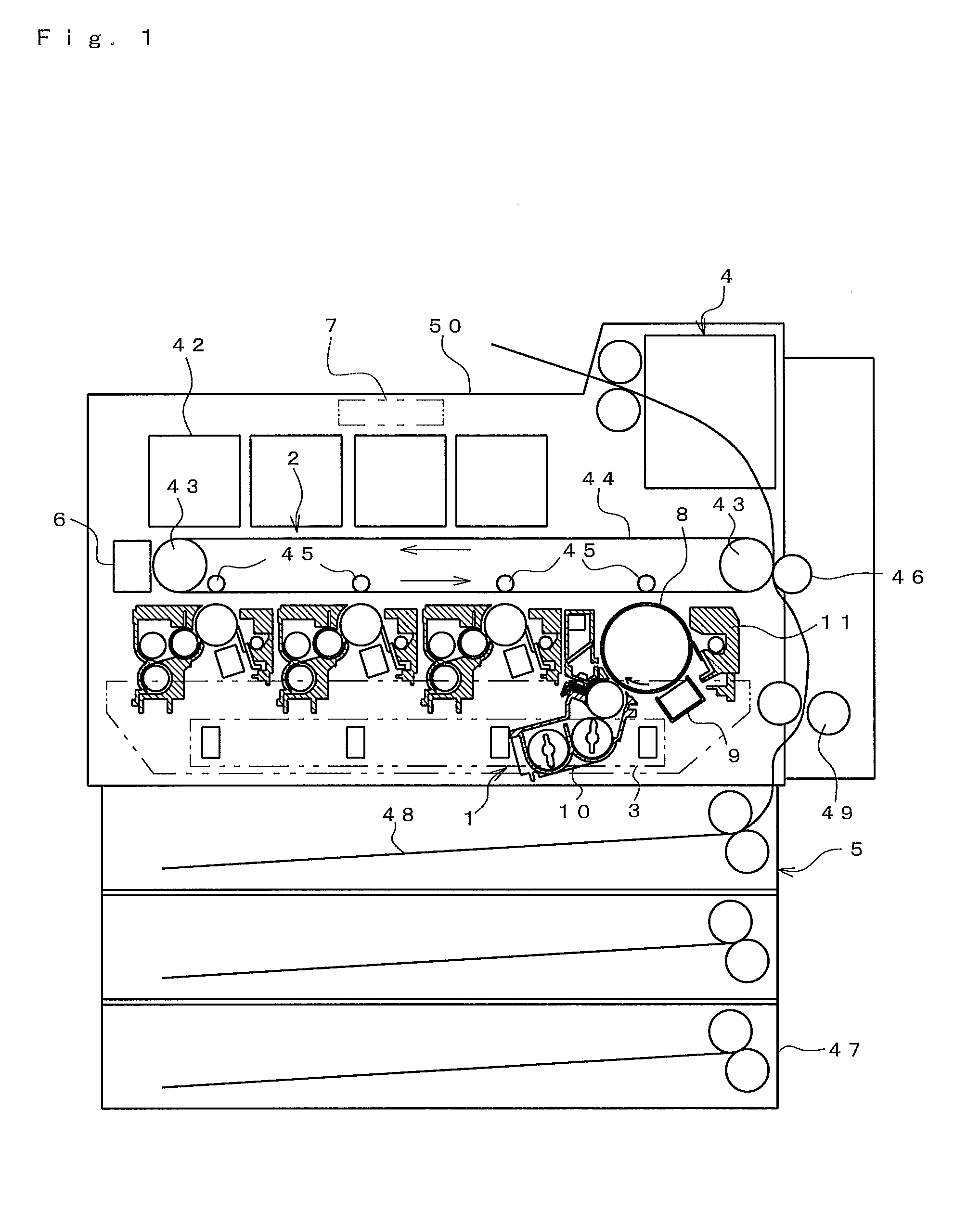
[0001]This application is based on Japanese Patent Application No. 2009-069767 filed in Japan on Mar. 23, 2009, the entire content of which is hereby incorporated by reference.BACKGROUND OF THE INVENTION[0002]1. Field of the Invention[0003]The present invention relates to a developing apparatus and an image forming apparatus.[0004]2. Description of the Related Art[0005]Conventionally, in a so-called trickle type image forming apparatus structured such as to discharge a developer including a deteriorated carrier, and replenish a new developer, for example, a structure having the following structured developing apparatus is known.[0006]In other words, there is known a developing apparatus structured such as to inhibit a lot of developers from being discharged all at once from a developing tank on the basis of a protruding portion, even if the developing tank is inclined, by forming the protruding portion allowing the developer to flow into the developing tank, and forming a discharge ...

Claims


Application Information

Patent Timeline
IPC IPC(8): G03G15/08
CPCG03G15/0808G03G2215/0822G03G15/0848
Inventor KIDO, HIROTO
Owner KONICA MINOLTA BUSINESS TECH INC
Learn More