Head for a powered denture brush and a denture brush incorporating the same

a denture brush and head technology, applied in the field of toothbrushes, can solve the problems of difficult use for the elderly or the infirm, difficulty in cleaning the teeth, and manual cleaning requires a significant amount of dexterity, and achieve the effects of easy cleaning of the bottom and sides, easy cleaning of the larger areas of teeth, and convenient us

Active Publication Date: 2010-09-30
HARRISON HYGIENE
View PDF7 Cites 30 Cited by
  • Summary
  • Abstract
  • Description
  • Claims
  • Application Information

AI Technical Summary

Benefits of technology

[0007]The device of the present invention comprises a head for a denture brush that is detachably connected to a powered handle and a denture brush incorporating the same. The head includes a housing having a first set of bristles extending outwardly from a first side and a second set of bristles extending outwardly from a second side. The first and second sets of bristles are mounted such that they are movable in response to rotation of a camshaft in the head. Some of the bristles on each side of the head may be linearly pulsed toward and away from the housing in a direction substantially orthogonal to a longitudinal axis of the head. Additionally, some of the bristles on each side of the head may be rotated about a horizontal axis that is orthogonal to the longitudinal axis. The bristles of the first set of bristles are configured to be longer and pointed so that they more easily fit into the grooved side of a denture. The bristles of the firs...

Problems solved by technology

However, manual cleaning requires a significant amount of dexterity and this may present a problem for older denture wea...

Method used


Image

  • Head for a powered denture brush and a denture brush incorporating the same
  • Head for a powered denture brush and a denture brush incorporating the same
  • Head for a powered denture brush and a denture brush incorporating the same

Examples


first embodiment

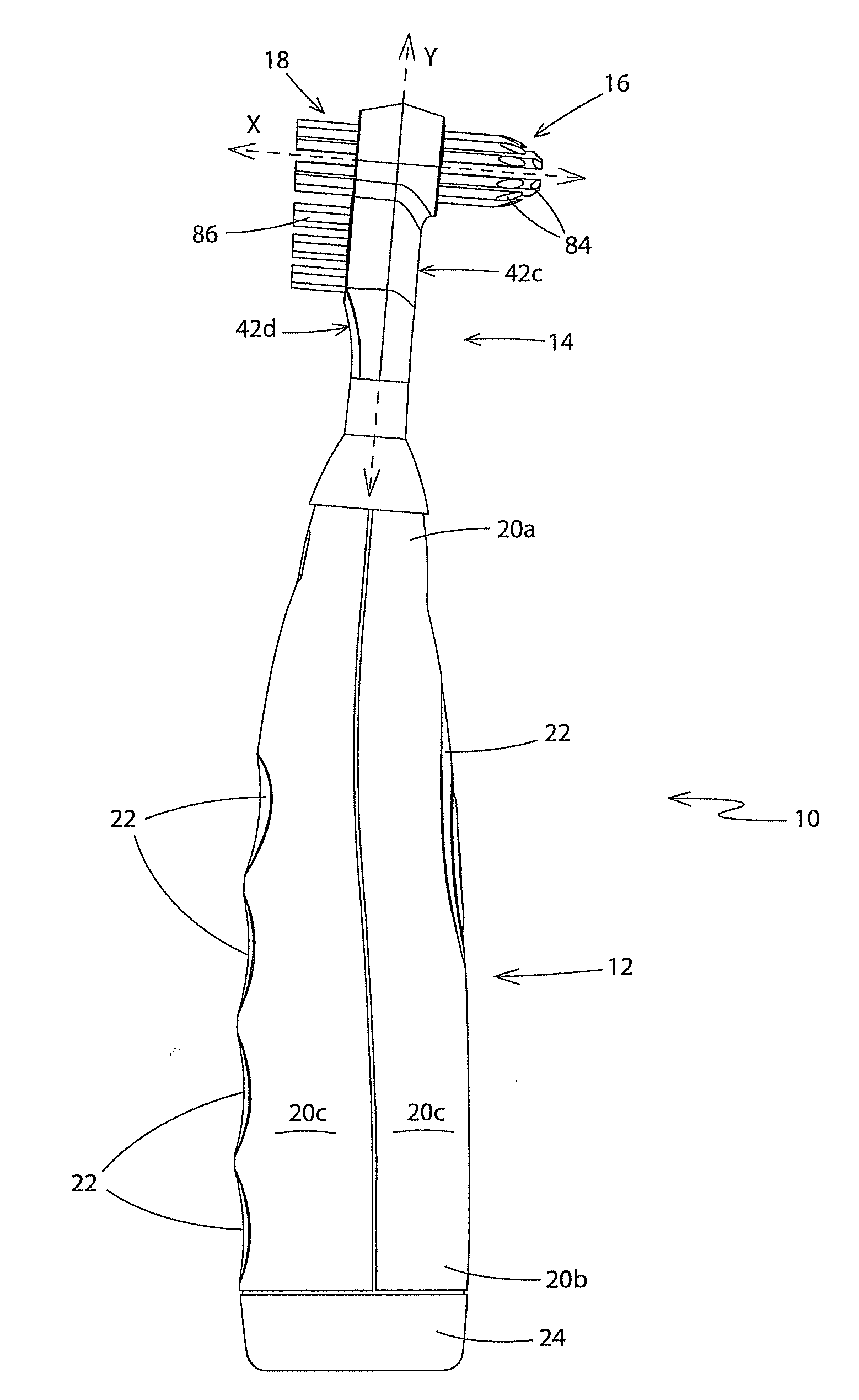
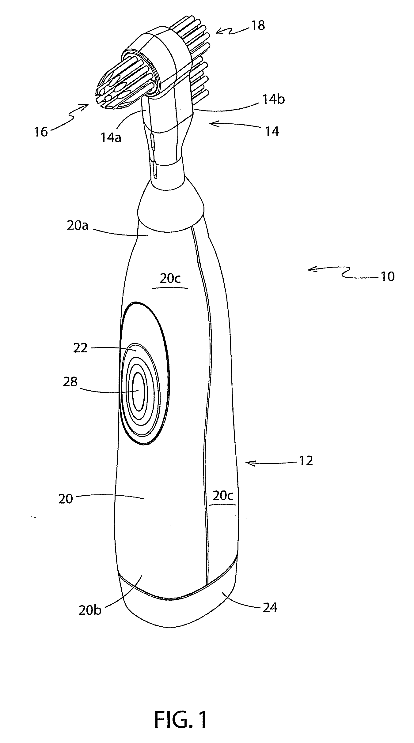
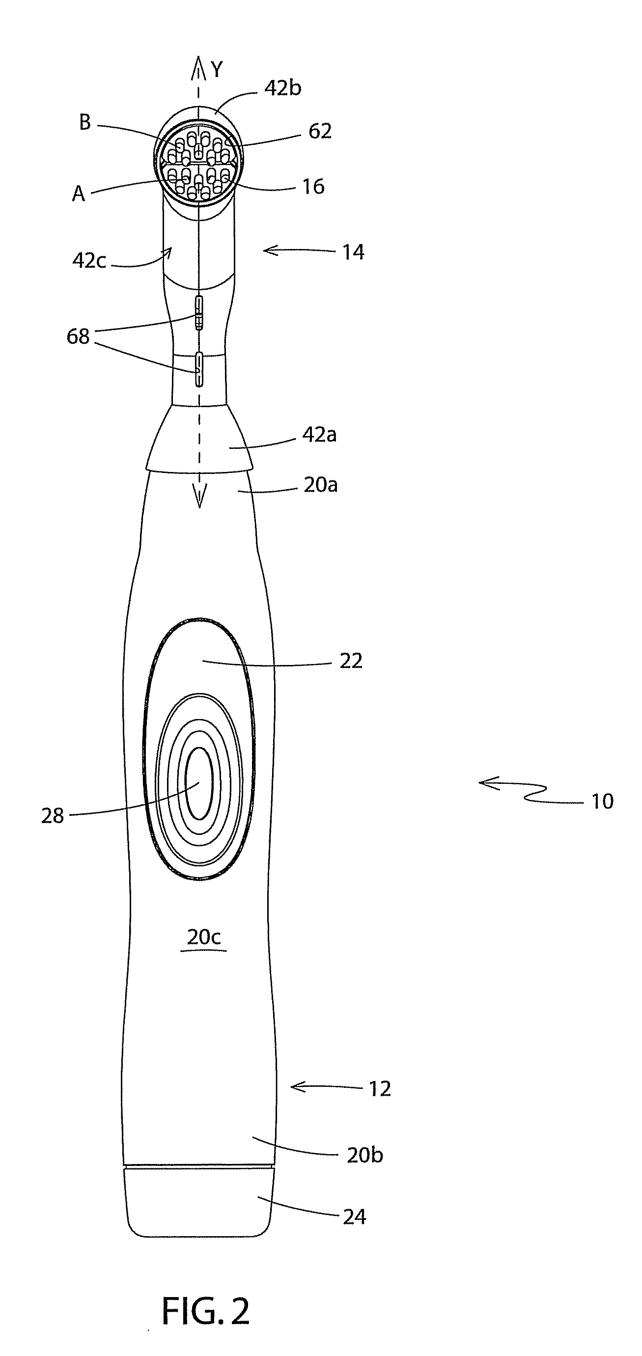
[0021]Referring to FIGS. 1-6 there is shown a powered denture brush in accordance with the present invention and generally indicated at 10. Brush 10 is designed for cleaning a denture 500 (FIGS. 9 & 10) that has both a teeth side 502 and a grooved side 504. Grooved side 504 is configured to receive a portion of the user's gum tissue therein and to be temporarily bonded thereto by way of a bonding agent. Brush 10 comprises a handle 12 and a head 14 that are detachably engageable with each other. As will be hereinafter described in greater detail, handle 12 includes a battery-operated drive mechanism that is operationally connected to components in head 14. Head 14 includes a first set of bristles 16 that extend outwardly away from a first side 14a of head 14 and a second set of bristles 18 that extend outwardly away from a second side 14b of head 14. The first set of bristles 16 is configured to clean gum-receiving groove 504 in a first side of denture 500 (FIG. 10). The second set o...

second embodiment

[0039]FIGS. 7a, 7b and 8 show the head of a powered denture brush in accordance with the present invention, with the head being generally referenced by the number 214. Head 214 is configured to be snap fitted to a powered handle such as handle 12 described previously herein. Head 214 is substantially identical to head 14 with the exception that there is a single first tuft block 270 that is substantially circular in cross sectional shape and that the camshaft 302 terminates in an angled slot 312 in first tuft block 270 instead of in a recess proximate the second end 242b of housing 242 as was the case with the previous embodiment. Consequently, when camshaft 302 is rotated by the drive shaft, first tuft block 270 is caused to rotate about the horizontal axis “X” (FIG. 8) instead of being linearly sliding in and out of the first and second apertures 262, 264. The rotation of first tuft block 270 about horizontal axis “X” is illustrated in FIGS. 7a and 7b. The first tuft block 270 the...


PUM


Abstract

A head for a denture brush that is detachably connected to a powered handle and a denture brush incorporating the same. The head includes a housing having a first set of bristles extending outwardly from a first side and a second set of bristles extending outwardly from a second side. The first and second sets of bristles are mounted such that they are movable in response to rotation of a camshaft in the head. Some of bristles on each side of the head may be linearly pulsed toward and away from the housing substantially orthogonally to a longitudinal axis of the head. Additionally, some of the bristles on each side of the head may be rotated about a horizontal axis that is orthogonal to the longitudinal axis.

Description

BACKGROUND OF THE INVENTION[0001]1. Technical Field[0002]This invention generally relates to toothbrushes. More particularly, the invention relates to a powered denture brush. Specifically, the invention relates to a powered denture brush that has a set of powered bristles on both of a first and second side of the head, where some of those bristles may be moved linearly toward and away from the side of the head and others may be rotated about an axis orthogonal to the longitudinal axis of the head.[0003]2. Background Information[0004]It is estimated that somewhere around thirty five-million people in North America have a full or partial set of dentures. The dentures tend to vary quite a bit in size and shape because of the variations in patients' jaws. The most common method of cleaning dentures that is currently in use is to remove the plate from the mouth and to place it into a denture cup holding a cleaning solution. One such suitable cleaning solution is that manufactured and so...

Claims


Application Information

Patent Timeline
IPC IPC(8): A46B13/00A46B7/04
CPCA46B2200/1073A61C17/036A61C17/349A61C17/3436A61C17/3463A61C17/222
Inventor HARRISON, JAMESDICKIE, ROBERT G.
Owner HARRISON HYGIENE
Why Eureka
Try Eureka