Separating apparatus

a technology of separating apparatus and filter, which is applied in the direction of gravity filter, filter, external electric electrostatic separator, etc., can solve the problems of small amount of dirt and dust passing through the separating apparatus and being carried to the motor-driven fan unit, and it is undesirable for dirt and dust particles to pass through the fan of the motor and the fan uni

Active Publication Date: 2010-09-30
DYSON TECH LTD
View PDF57 Cites 63 Cited by
  • Summary
  • Abstract
  • Description
  • Claims
  • Application Information

AI Technical Summary

Benefits of technology

[0009]This advantageously provides a compact structure. In a preferred embodiment the filter may be a barrier filter. As used herein the term “barrier filter” shall be taken to mean a filter which captures and holds dirt and dust particles within the body of the filter.

Problems solved by technology

Irrespective of the type of separating apparatus used, there may be a risk of a small amount of dirt and dust passing through the separating apparatus and being carried to the motor-driven fan unit.
It is undesirable for dirt and dust particles to pass through the fan of a motor and fan unit because the fan may become damaged or may operate less efficiently.

Method used


Image

  • Separating apparatus
  • Separating apparatus
  • Separating apparatus

Examples


Embodiment Construction

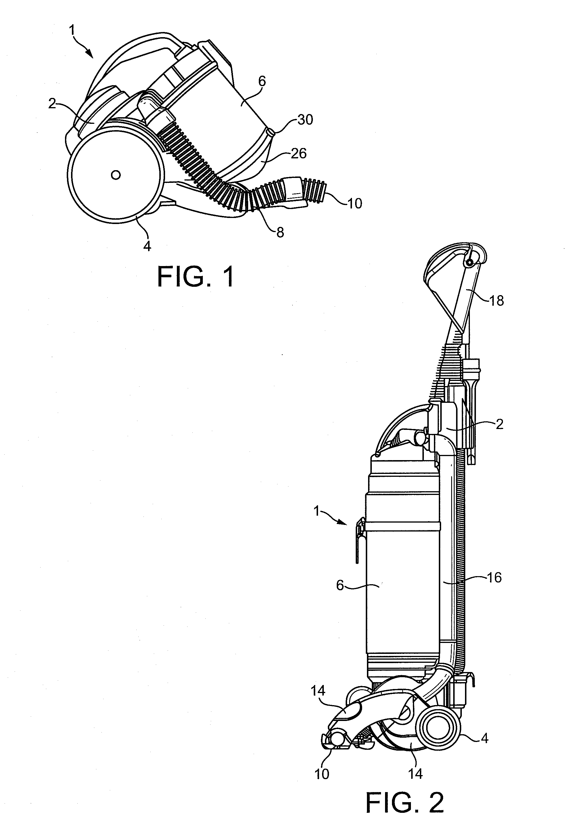
[0043]With reference to FIGS. 1 and 2 a vacuum cleaner is shown and indicated generally by the reference numeral 1.

[0044]In FIG. 1 the vacuum cleaner 1 comprises a main body 2, wheels 4 mounted on the main body 2 for manoeuvring the vacuum cleaner 1 across a surface to be cleaned, and a separating apparatus 6 removably mounted on the main body 2. A hose 8 communicates with the separating apparatus 6 and a motor and fan unit (not shown) is housed within the main body 2 for drawing dust laden air into the separating apparatus 6 via the hose 8. Commonly, a floor-engaging cleaner head (not shown) is coupled to the distal end of the hose 8 via a wand to facilitate manipulation of a dirty air inlet 10 over the surface to be cleaned.

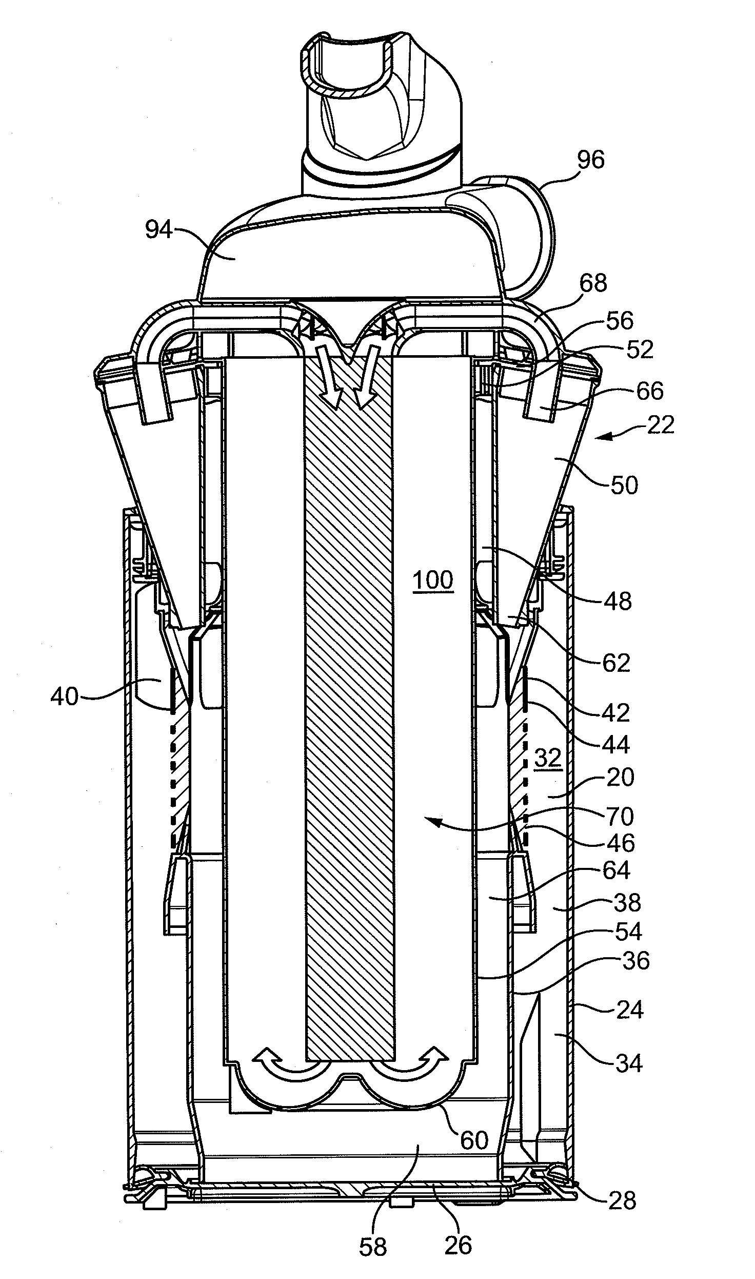
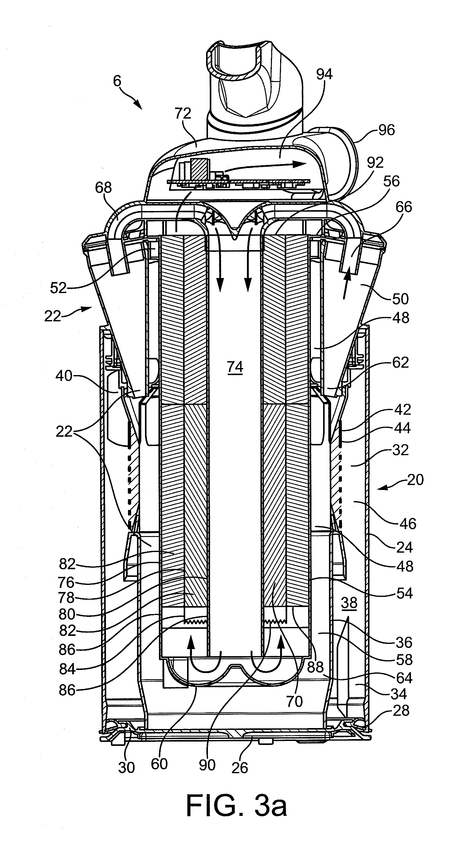
[0045]In use, dust laden air drawn into the separating apparatus 6 via the hose 8 has the dust particles separated from it in the separating apparatus 6. The dirt and dust is collected within the separating apparatus 6 while the cleaned air is channeled past th...


PUM

PropertyMeasurementUnit
angleaaaaaaaaaa
voltageaaaaaaaaaa
shapeaaaaaaaaaa

Abstract

The present invention relates to a separating apparatus for separating particles from a fluid flow. Particularly, but not exclusively, the invention relates to a vacuum cleaner having such a separating apparatus for removing dust particles from a dust laden airstream. The separating apparatus includes a first cyclonic cleaning stage, a second cyclonic cleaning stage arranged downstream from the first cyclonic cleaning stage, and an elongate filter arranged downstream from the second cyclonic cleaning stage, wherein the filter is at least partially surrounded by the first cyclonic cleaning stage.

Description

REFERENCE TO RELATED APPLICATIONS[0001]This application claims the priority of United Kingdom Application No. 0905500.5 filed Mar. 31, 2009 and United Kingdom Application No. 0912938.8 filed Jul. 24, 2009 the entire contents of which are incorporated herein by reference.FIELD OF THE INVENTION[0002]The present invention relates to a separating apparatus for separating particles from a fluid flow. Particularly, but not exclusively, the invention relates to a vacuum cleaner having such a separating apparatus for removing dust particles from a dust laden airstream.BACKGROUND OF THE INVENTION[0003]Known separating apparatus include those used in vacuum cleaners, for example cyclonic separating apparatus. Such cyclonic separating apparatus are known to comprise a low efficiency cyclone for separating relatively large particles and a high efficiency cyclone located downstream of the low efficiency cyclone for separating the fine particles which remain entrained within the airflow (see, for...

Claims


Application Information

Patent Timeline
Patent Type & Authority Applications(United States)
IPC IPC(8): A47L9/16B01D50/00B03C3/15
CPCA47L9/127A47L9/1633A47L9/1641Y10S55/03B01D46/0032B01D46/106B01D50/002B01D45/12B01D50/20B01D50/00A47L9/12A47L9/16
Inventor HORNE, LUCASJUPE, MATTHEW ROBERTWORKER, DAVID COLINSTEADMAN, GUILLAUME KRISTIAN
Owner DYSON TECH LTD
Why Eureka
Try Eureka