Air purifier

Inactive Publication Date: 2011-05-05
WU FU CHI
View PDF14 Cites 49 Cited by
  • Summary
  • Abstract
  • Description
  • Claims
  • Application Information

AI Technical Summary

Benefits of technology

[0007]The present invention has been accomplished under the circumstances in view. It is one object of the present invention to provide an air purifier, which uses an electric fan to cause formation of convection currents circulating upwardly through a longitudinal air passage and air filter elements in the longitudinal air passage, thereby effectively cleaning the air.
[0008]To achieve this and other objects of the present invention, an air purifier comprises a housing for positioning on the floor, the housing comprising an air intake port with open end located on a bottom side thereof and spaced above the floor for guiding in outside air, an air output port located on a top side thereof for guiding inside air out of the housing, a longitudinal air passage in air communication between the air intake port and the air output port; a wire gauze filter covered on the air output port of the housing; a plurality of air filter elements mounted in the longitudinal air passage inside the housing for removing solid matters from air passing through the longitudinal air passage; and at least one electric fan mounted in the longitudinal air passage inside the housing and controlled to draw outside air around the floor into the air intake port toward the air output port. Subject to the design of the vertically or substantially vertically exte

Problems solved by technology

However, waste gas from industries, automobiles and other transportation vehicles affects the quality of water, sunlight and air around people, threatening human health.
However, the air around us contains invisible harmful substances.
These harmful substances will fall to or floating nearly above the floor, table top and desk top subject to the effect of gravity when it is still.
When a wind is induced as we are walking or when a natural wind occurs, the harmful substances deposited on or floating nearly above the floor, table top or desk top will be moved with the wind upwards into the higher level of the indoor air, and people within this area will breathe in these harmful substances, causing diseases to occur.
However, the air intake p

Method used


Image

  • Air purifier
  • Air purifier
  • Air purifier

Examples


Embodiment Construction

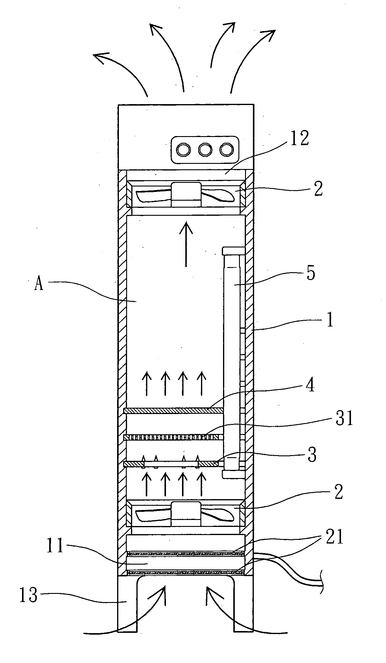
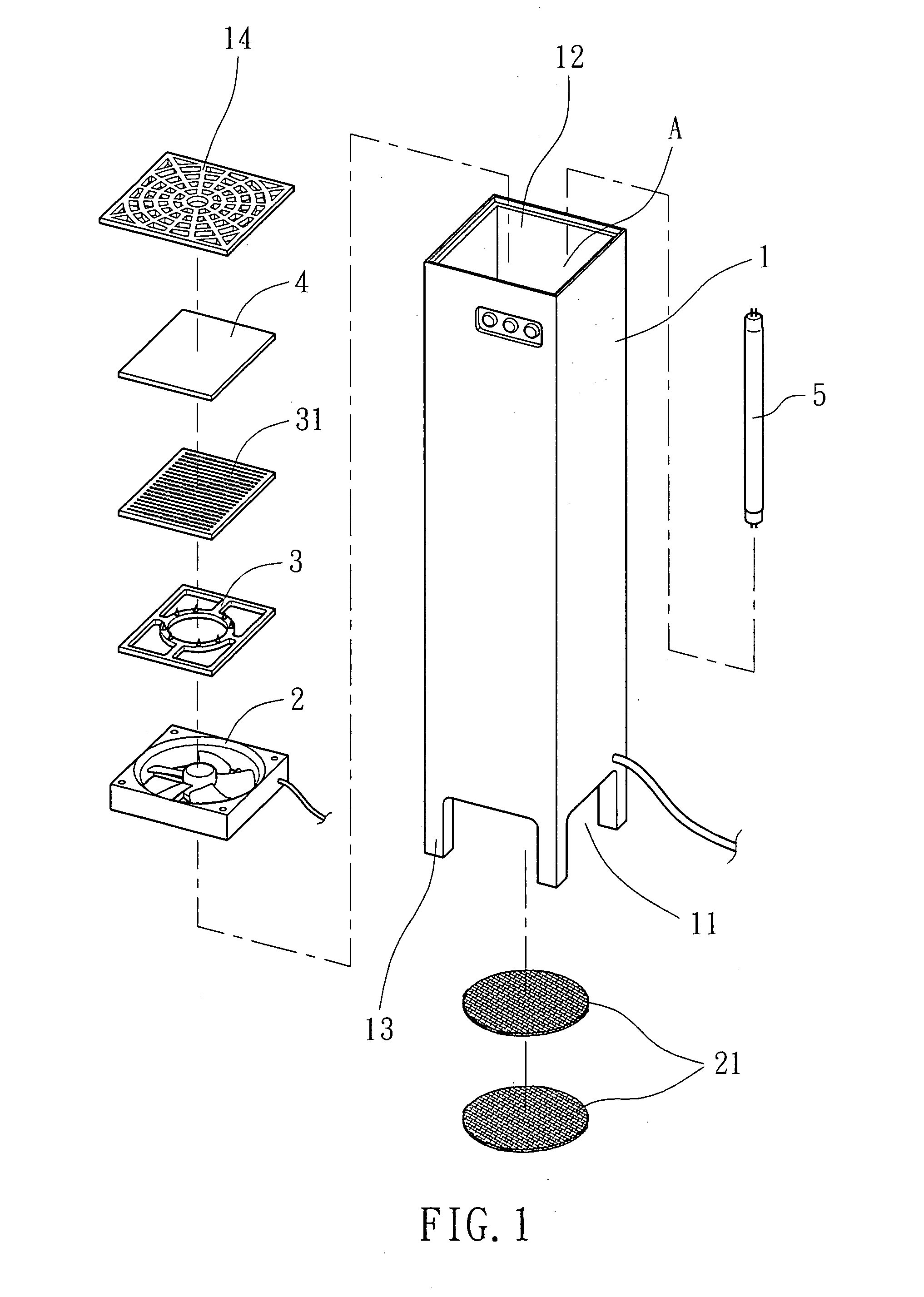
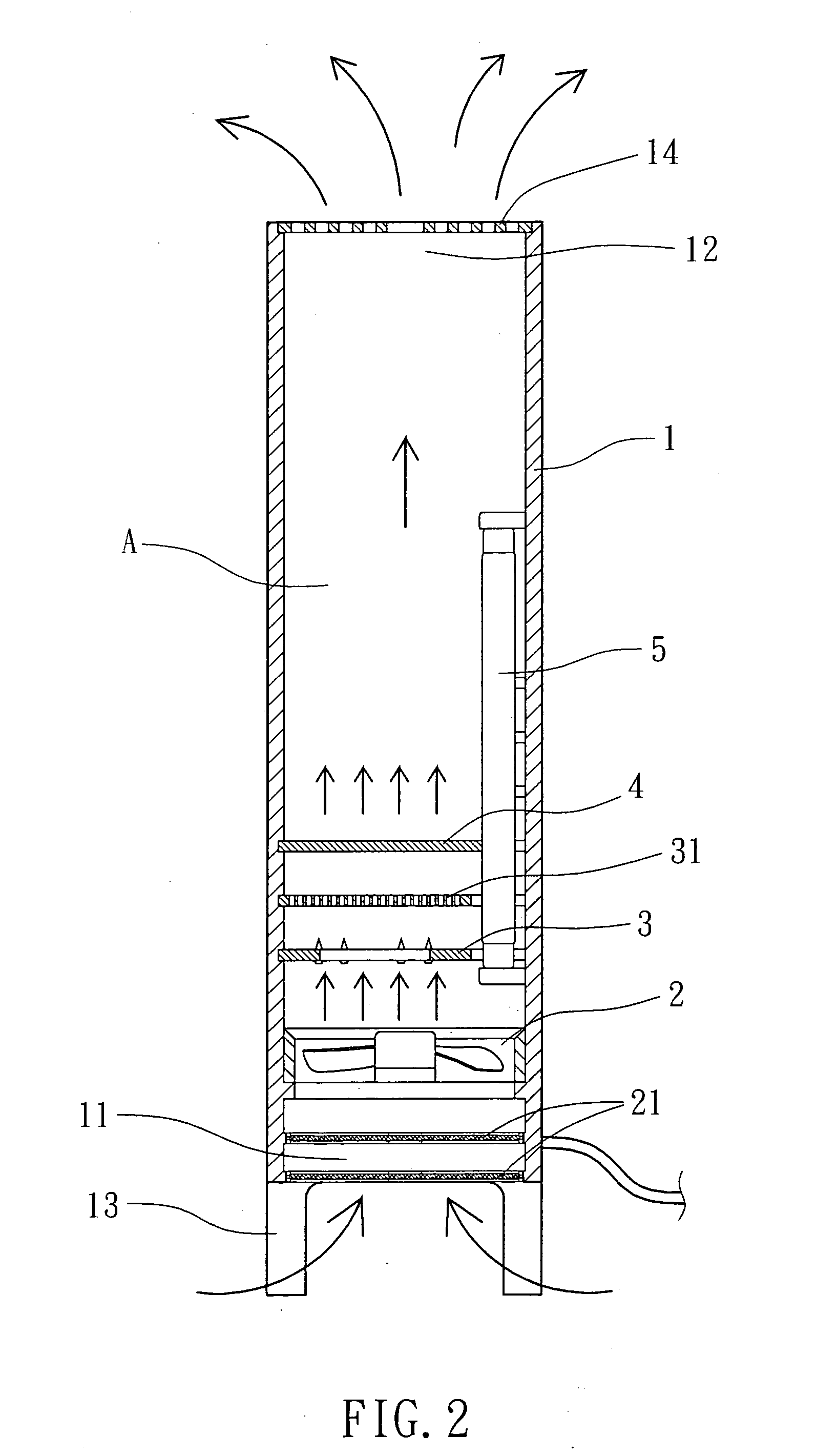
[0019]Referring to FIGS. 1˜4, an air purifier in accordance with a first embodiment of the present invention is shown comprising a housing 1, a wire gauze filter 14, an electric fan 2, two air filter elements 21, an ionizer 3, an electro-static precipitator 31, a photo catalytic panel 4, an ultraviolet lamp 5.

[0020]The housing 1 comprises an air intake port 11 located on the bottom side thereof, an air output port 12 located on the top side thereof, a longitudinal air passage A in air communication between the air intake port 11 and the air output port 12 and a plurality of legs 13 spaced around the bottom side for positioning on the floor to keep the air intake port 11 above the floor at a predetermined distance.

[0021]The wire gauze filter 14 is covered on the air output port 12 of the housing 1.

[0022]The electric fan 2 is transversely mounted in the longitudinal air passage A inside the housing 1 near the air intake port 11, and controlled to draw outside air from the space around...


PUM

PropertyMeasurementUnit
Pressureaaaaaaaaaa
Flow rateaaaaaaaaaa
Concentrationaaaaaaaaaa

Abstract

An air purifier includes a vertically disposed housing provided with a wire gauze filter, electric fans and air filter elements. The electric fans draw outside air around the floor vertically into the bottom air intake port toward the top air output port of the housing so that the flow of air, when passed out of the air output port, flows upwards to a certain elevation and is then diffused and lowered in all directions around the housing. By means of the traction of the flow of air, the pressure difference of the convection of air between the low air pressure and the high air pressure at the bottom and top sides of the housing, high concentration of car waste gas, micro dust particles, hair dust, micro fibers and other harmful industrial odors that fall to the floor due to the effect of gravity or floating nearly above the floor are sucked into the inside of the housing by the low air pressure zone at the open bottom side of the housing and then removed by the filter elements.

Description

BACKGROUND OF THE INVENTION[0001]1. Field of the Invention[0002]The present invention relates to air cleaning technology and more particularly, to an air purifier, which comprises a housing disposed perpendicular to the floor and having its air intake port disposed at the bottom side and its air output port disposed at the top side so that the electric fan that is mounted inside of the housing draws in air from the open bottom air intake port for causing the intake flow of air to go upwardly through a longitudinal air passage of the housing to the outside via the top air output port, thereby forming a pressure difference of convection of air between a low air pressure at the open bottom side and a high air pressure at the top side. When the flow of air goes upwardly out of the air output port, it flows upwards to a certain elevation and is then diffused and lowered in all directions from the center of the housing. By means of the traction of the flow of air during continuous operati...

Claims


Application Information

Patent Timeline
IPC IPC(8): B03C3/011B03C3/36B03C3/016B03C3/38B01D27/08
CPCB01D46/0024B01D46/12B01D2273/30B03C3/011B03C3/016F24F2003/1667B03C3/155B03C3/368F24F3/166F24F2001/0096F24F2003/1635B03C3/017F24F1/0071Y02A50/20Y02A50/2351F24F8/194F24F8/22F24F8/192B01D46/64
Inventor WU, FU-CHI
Owner WU FU CHI
Why Eureka
Try Eureka