Vacuum cleaner

a vacuum cleaner and vacuum cleaner technology, applied in the field of vacuum cleaners, can solve the problems of low power factor and unfavorable electric supply situation of power companies, and achieve the effect of high suction for

Inactive Publication Date: 2007-06-21
PANASONIC CORP
View PDF3 Cites 52 Cited by
  • Summary
  • Abstract
  • Description
  • Claims
  • Application Information

AI Technical Summary

Benefits of technology

[0006] It is, therefore, an object of the present invention to provide a vacuum cleaner capable of suppressing a load current to be equal to or lower than a predetermined level while maintaining a high suction force regardless of an amount of collected dust, and further, eliminating the necessity for the user or the power company to examine whether a current rating for the power distribution system has to be reset.

Problems solved by technology

However, in this region, a total current is not reduced, because a reactive power is high and thus a power factor is low.
This is not a favorable situation for a power company supplying the electric power.

Method used


Image

  • Vacuum cleaner
  • Vacuum cleaner
  • Vacuum cleaner

Examples


first embodiment

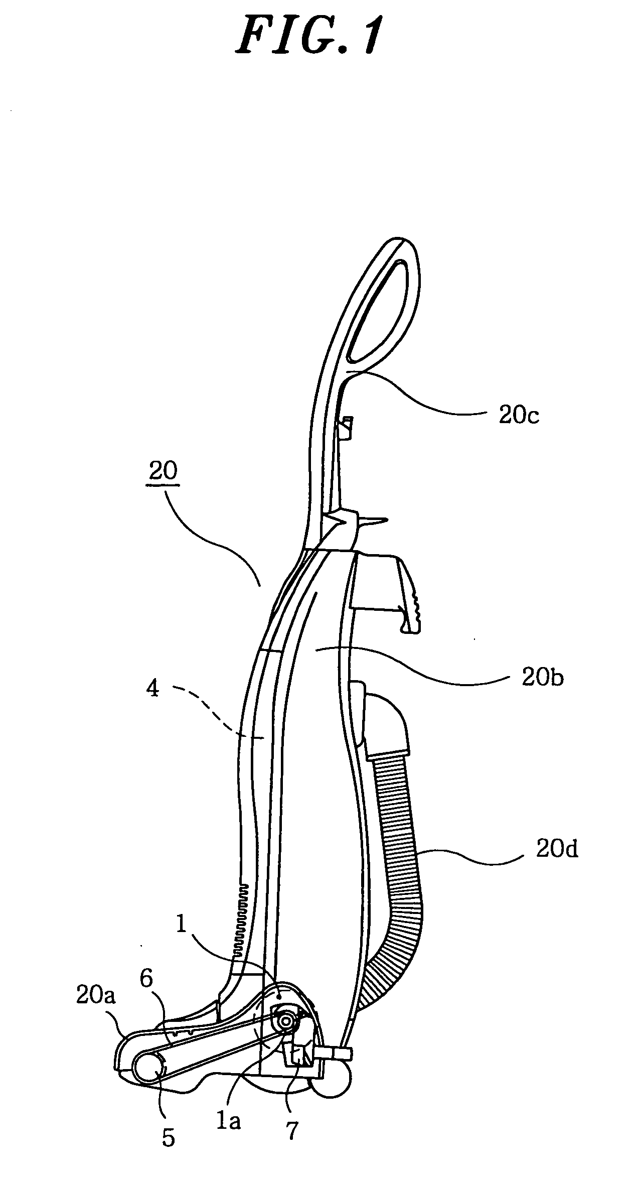
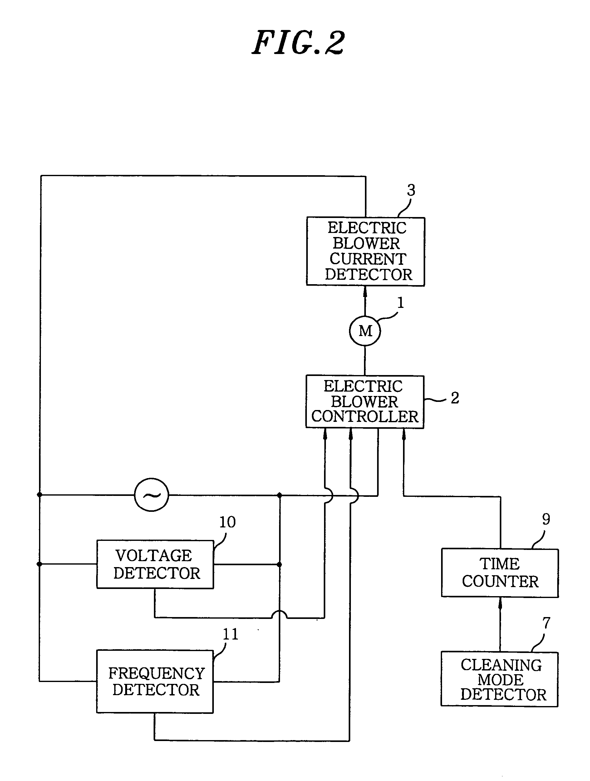
[0027] A vacuum cleaner in accordance with a first preferred embodiment of the present invention will be described with reference to FIGS. 1 to 4. FIG. 1 shows an exterior view of a vacuum cleaner in accordance with a first preferred embodiment of the present invention; and FIG. 2 describes a circuit block diagram of the vacuum cleaner in accordance with the first preferred embodiment of the present invention.

[0028] Referring to FIGS. 1 and 2, there is illustrated vacuum cleaner main body 20 including bottom nozzle 20a accommodating therein rotational brush 5 for brushing up dust particles; main body 20b, tiltably connected to bottom nozzle 20a, for accommodating therein electric blower 1 for sucking dust particles in and having dust chamber 4 for collecting the dust particles sucked in; manipulating handle 20c fixed to an upper end of main body 20b; and hose 20d for connecting dust chamber 4 with bottom nozzle 20a for communicating therewith.

[0029] Electric blower controller 2 co...

second embodiment

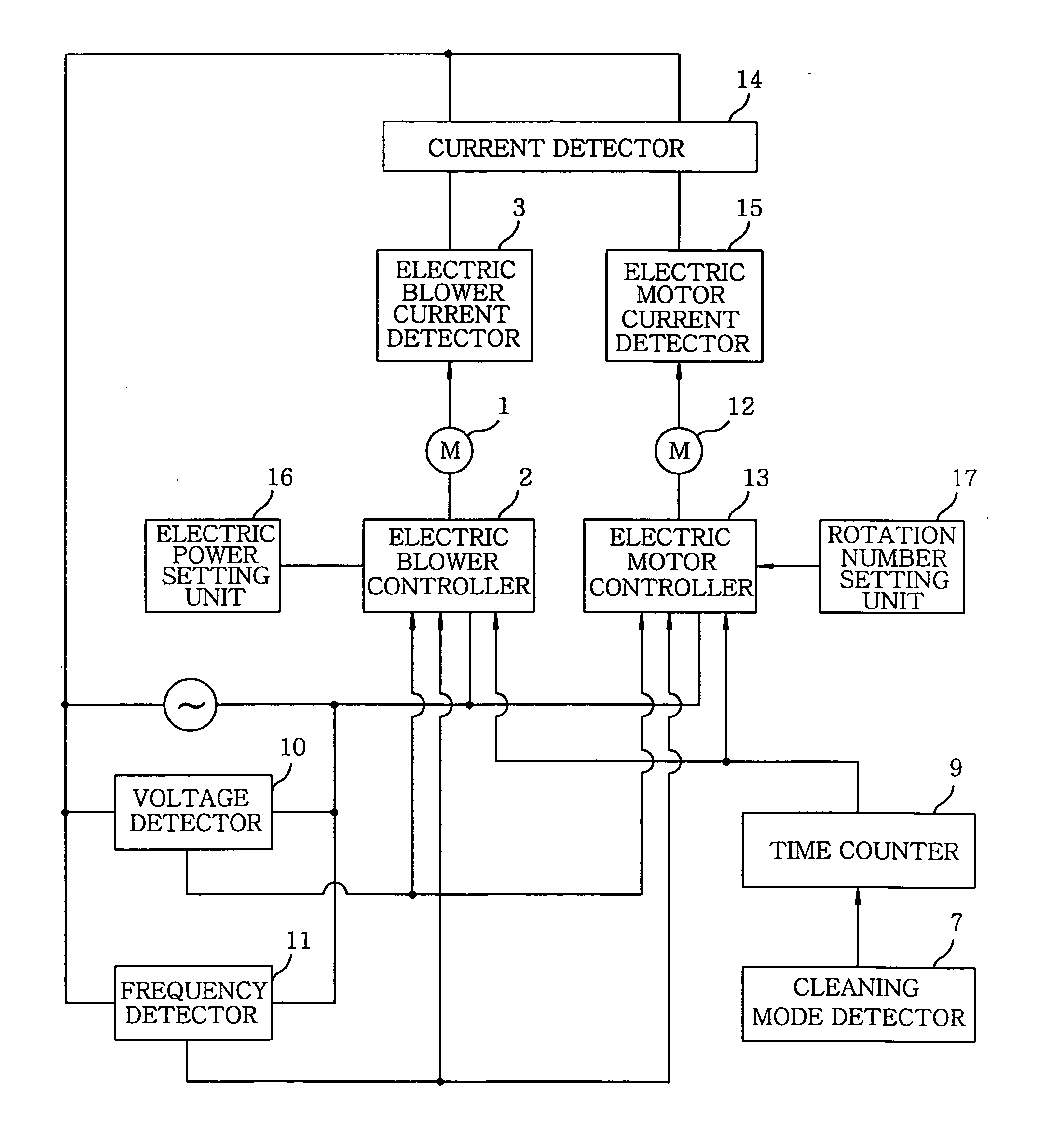
[0048]FIG. 5 offers an exterior view of a vacuum cleaner in accordance with a second preferred embodiment of the present invention; and FIG. 6 depicts a circuit block diagram of the vacuum cleaner in accordance with the second preferred embodiment of the present invention. Detailed explanations of parts identical or similar to those described in the first preferred embodiment will be omitted, and like reference numerals will be used therefor.

[0049] In the first preferred embodiment, rotational brush 5 is driven to be rotated by electric blower 1. However, in the present embodiment, electric motor 12 for rotating rotational brush 5 is provided and driven independently from electric blower 1.

[0050] Referring to FIGS. 5 and 6, there are illustrated electric motor controller 13 for controlling the number of rotation of electric motor 12; electric motor current detector 15 for detecting a current flowing in electric motor 12; electric blower current detector 3 for detecting a current f...


PUM


Abstract

A vacuum cleaner includes an electric blower; an electric blower controller for controlling the electric blower; an electric blower current detector for detecting at least a current flowing in the electric blower; and a dust chamber provided at an upstream of the electric blower, for collecting dust particles sucked by the electric blower. A predetermined level of a current is made to flow in the electric blower regardless of a dust particle amount in the dust chamber. Preferably, the vacuum cleaner further includes voltage detector for detecting a voltage of a power supply applied to the vacuum cleaner. More preferably, the vacuum cleaner further includes a frequency detector for detecting a frequency of a power supply applied to the vacuum cleaner.

Description

FIELD OF THE INVENTION [0001] The present invention relates to a vacuum cleaner; and, more particularly, to a vacuum cleaner in which an electric current flowing therein can be controlled. BACKGROUND OF THE INVENTION [0002] Recently, there have been developed vacuum cleaners in which electric powers provided to electric blowers therein can be controlled by detecting negative pressures inside the vacuum cleaners in order to improve suction forces. Further, in some vacuum cleaners, power consumptions are controlled to be reduced when suction flow rates are higher than a specific level while amounts of collected dust are low (see, for example, Japanese Patent No. 3326126). [0003]FIG. 7 shows a graph representing an electric power and a current as a function of a suction flow rate in accordance with the power control method disclosed in Japanese Patent No. 3326126. As shown therein, the electric power represented as an effective power is reduced where the suction flow rate gets high. Ho...

Claims


Application Information

Patent Timeline
Patent Type & Authority Applications(United States)
IPC IPC(8): A47L5/00
CPCA47L9/2805A47L9/2831A47L9/2842A47L9/2847A47L9/28A47L9/00
Inventor FUJIWARA, TOSIAKINAKAO, HIROSHITAKAHASHI, MASAKIHAYASI, NOBUHIRO
Owner PANASONIC CORP
Why Eureka
Try Eureka