Slide type circular saw

a circular saw and sliding technology, applied in the field of sliding type circular saws, can solve the problems of low rigidity and cutting accuracy, and achieve the effects of high rigidity, good operating feel of sliding saw units, and good cutting accuracy

Active Publication Date: 2010-09-30
MAKITA CORP
View PDF20 Cites 14 Cited by
  • Summary
  • Abstract
  • Description
  • Claims
  • Application Information

AI Technical Summary

Benefits of technology

[0022]According to the above-described configuration (1), a high degree of rigidity and cutting accuracy can be ensured while a good operating feel of sliding a saw unit can be retained.
[0023]With the feature (2) or (3), in addition to the advantages described above in relation to the configuration (1), since the pressing member is implemented as setscrew(s), the pressing member can easily be obtained without impairing the ease of assembly.
[0024]With the feature (4), in addition to the advantages described above in relation to the configuration (1) with or without the feature (2), the restrictions on the press-fitted bearing parts and the free play of the loosely inserted bearing part can be well balanced, while the number of bearing parts can be reduced.
[0025]With the feature (5), in addition to the advantages described above in relation to the configuration (1), the connection can be established more easily in comparison with the case with press fitting, and thus the ease of assembly can be increased.
[0026]With the feature (6), as well, in addition to the advantages described above in relation to the configuration (1), the connection can be established more easily in comparison with the case with press fitting, and thus the ease of assembly can be increased.

Problems solved by technology

On the other hand, however, the loose insertion would disadvantageously produce a wobble and / or twisting, which would possibly lower the rigidity and cutting accuracy.

Method used


Image

  • Slide type circular saw
  • Slide type circular saw
  • Slide type circular saw

Examples


Embodiment Construction

[0037]Exemplary embodiments of the present invention will be described hereinafter with reference to the accompanying drawings.

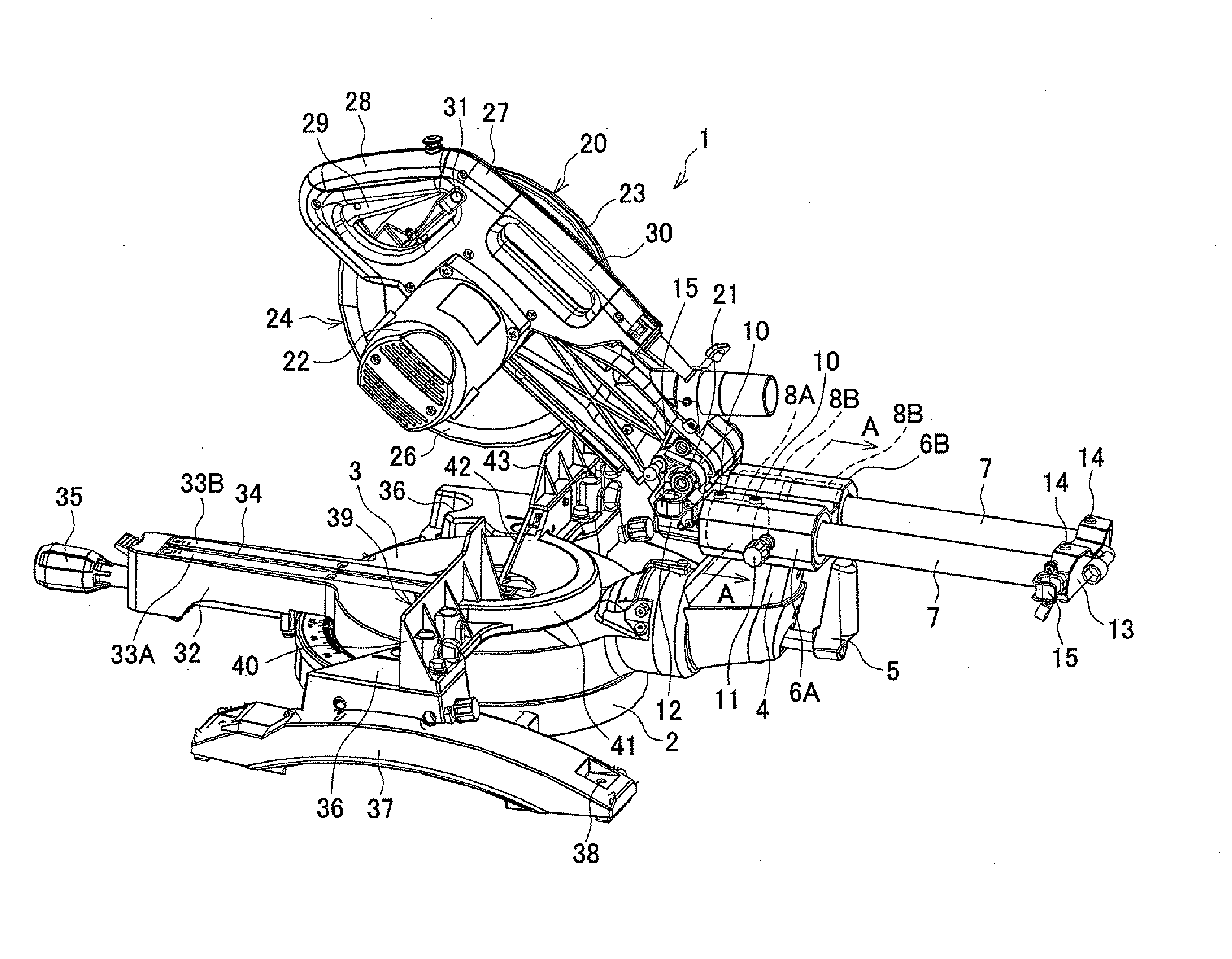
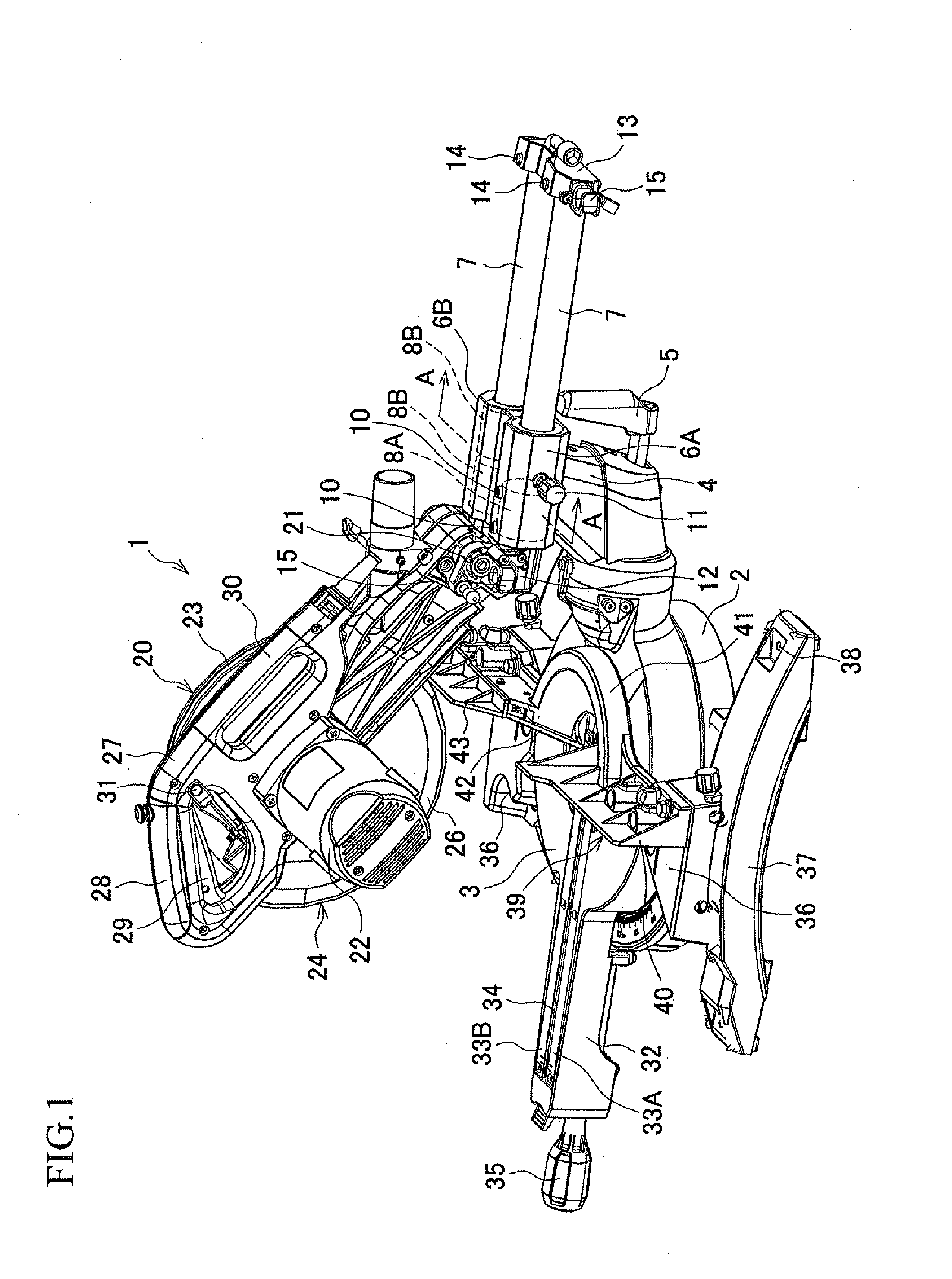
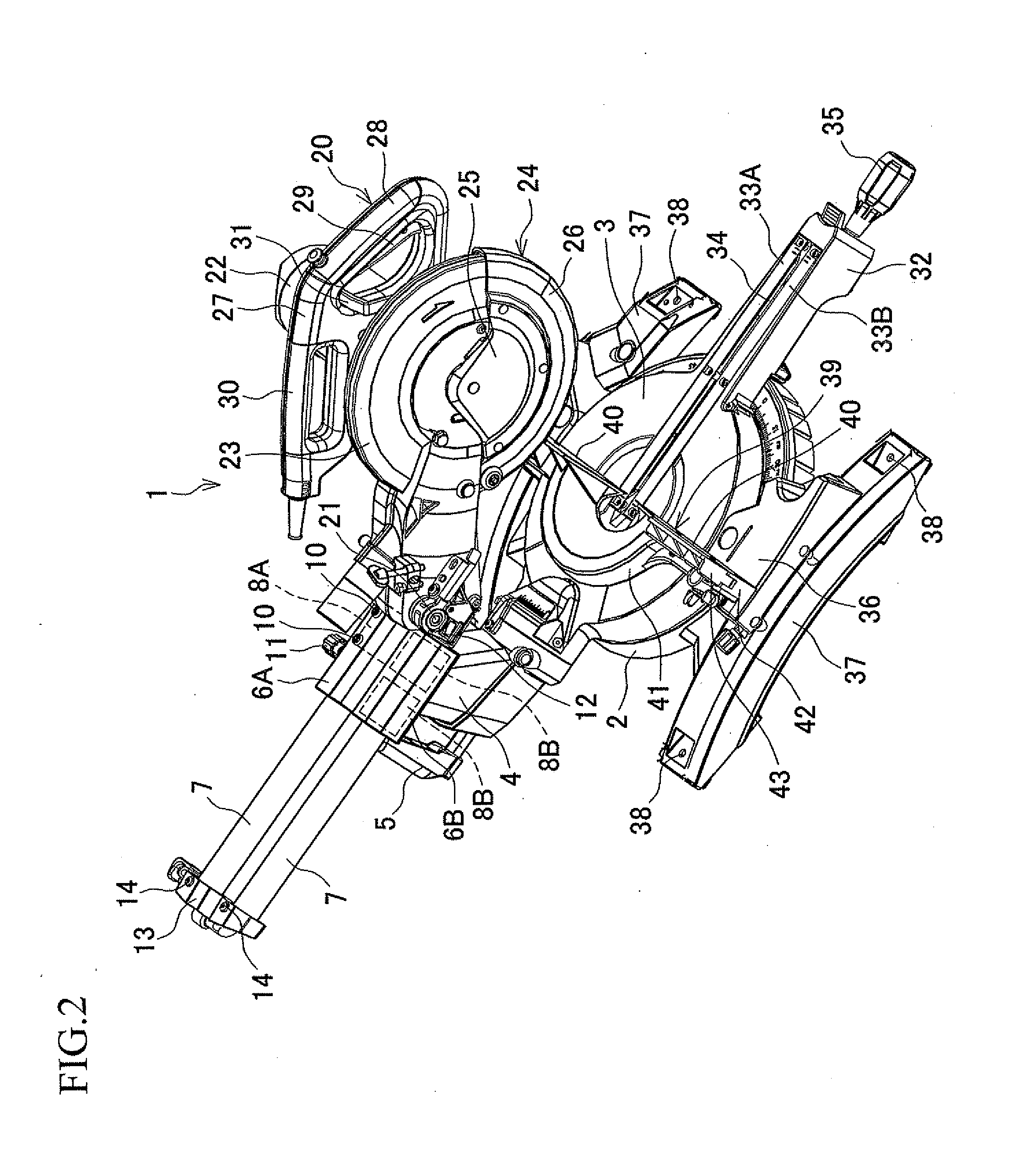
[0038]Referring now to FIGS. 1 and 2, which are perspective views showing an exemplified embodiment of the present invention, a slide type circular saw 1 includes a base 2 and a saw unit 20, and the base 2 includes a turn base 3 and an arm 4. The turn base 3 is a table circular in shape as viewed from above, which is placed at a center of the base 2 and can be swiveled thereon. The arm 4 has a lever 5 with which the arm 4 can be tilted to the left and to the right up to 45 degrees at the maximum and can be fixed at a desired angle. At an upper end of the arm 4, as also shown in FIG. 3, tubular holding portions 6A, GB arranged parallel to each other, extending in the front-rear direction, are provided in a pair as an integral part. Left and right pipe-like slide bars 7 are slidably supported by linear ball bearings 8A, 8B, which serve as bearing parts, in suc...


PUM

PropertyMeasurementUnit
angleaaaaaaaaaa
dimensionaaaaaaaaaa
rigidityaaaaaaaaaa

Abstract

In a slide type circular saw, slide bars extending parallel to each other in a front-rear direction are slidably supported by bearing parts provided in first and second holding portions. The bearing part included in the first holding portion is press-fitted therein, while the bearing part included in the second holding portion is loosely inserted therein, and the second holding portion includes a pressing member which is configured to press the bearing part of the second holding portion against an inner surface of the second holding portion in a direction perpendicular to a plane which contains axes of the slide bars.

Description

BACKGROUND OF THE INVENTION[0001]This application claims the entire benefit of Japanese Patent Application Number 2009-077151 filed on Mar. 26, 2009, the entirety of which is incorporated by reference.TECHNICAL FIELD[0002]This invention relates to a slide type circular saw in which a saw unit having a saw blade is provided above a base and is configured to be slidable frontward and rearward relative to the base.BACKGROUND ART[0003]In the slide type circular saw, a saw unit having a motor-driven rotary blade is provided above a base, and configured to be slidable frontward and rearward relative to the base by a slide mechanism, so that even a workpiece having a large dimension in the front-rear direction can be cut through operations of lowering and sliding the saw unit. The slide mechanism, well known in the art as disclosed in Japanese Examined Utility Model Application Publication No. 6-7859, includes an arm stood at the base, a holding member provided at an upper end of the arm, ...

Claims


Application Information

Patent Timeline
Patent Type & Authority Applications(United States)
IPC IPC(8): B23D45/02B23D45/04
CPCB23D45/024B27B27/08B27B5/29B23D47/02Y10T83/7693
Inventor SASAKI, KATSUHIKOINAI, MASAHIKO
Owner MAKITA CORP
Why Eureka
Try Eureka