Compact tools with suction cups for handling robot

a tooling and robot technology, applied in manipulators, packaging, packaging foodstuffs, etc., can solve the problems of over-engineering of present-day robots in relation to payloads, inability to exploit the best of their capabilities, and heavy tooling, so as to reduce the noise of compressed air escaping

Inactive Publication Date: 2010-09-30
SIDEL PARTICIPATIONS SAS
View PDF9 Cites 22 Cited by
  • Summary
  • Abstract
  • Description
  • Claims
  • Application Information

AI Technical Summary

Benefits of technology

[0029]Still in this preferred embodiment of the invention, the bores accommodating the various cartridges open, at one side, into a common compressed air inlet chamber which compressed air supplies the upstream part of the cartridges and, on the other side, that is to say on the exhaust

Problems solved by technology

Because the tooling is very heavy in relation to the mass of the products that are to be manipulated, such as sachets or pouches for example, present-day robots are over-engineered in relation to the payload that they are to handle.
More “lightweight” robots do exist and these are also generally very high speed but cannot be exploited to the best of their capabilities because, firstly, of the weight of the tooling used and, secondly, of their acceleration and speed of movement capabilities.
The problem is that this speed of movement generates accelerations that soon become problematic, accelerations which are somewhat incompatible with the holding system w

Method used


Image

  • Compact tools with suction cups for handling robot
  • Compact tools with suction cups for handling robot
  • Compact tools with suction cups for handling robot

Examples


Embodiment Construction

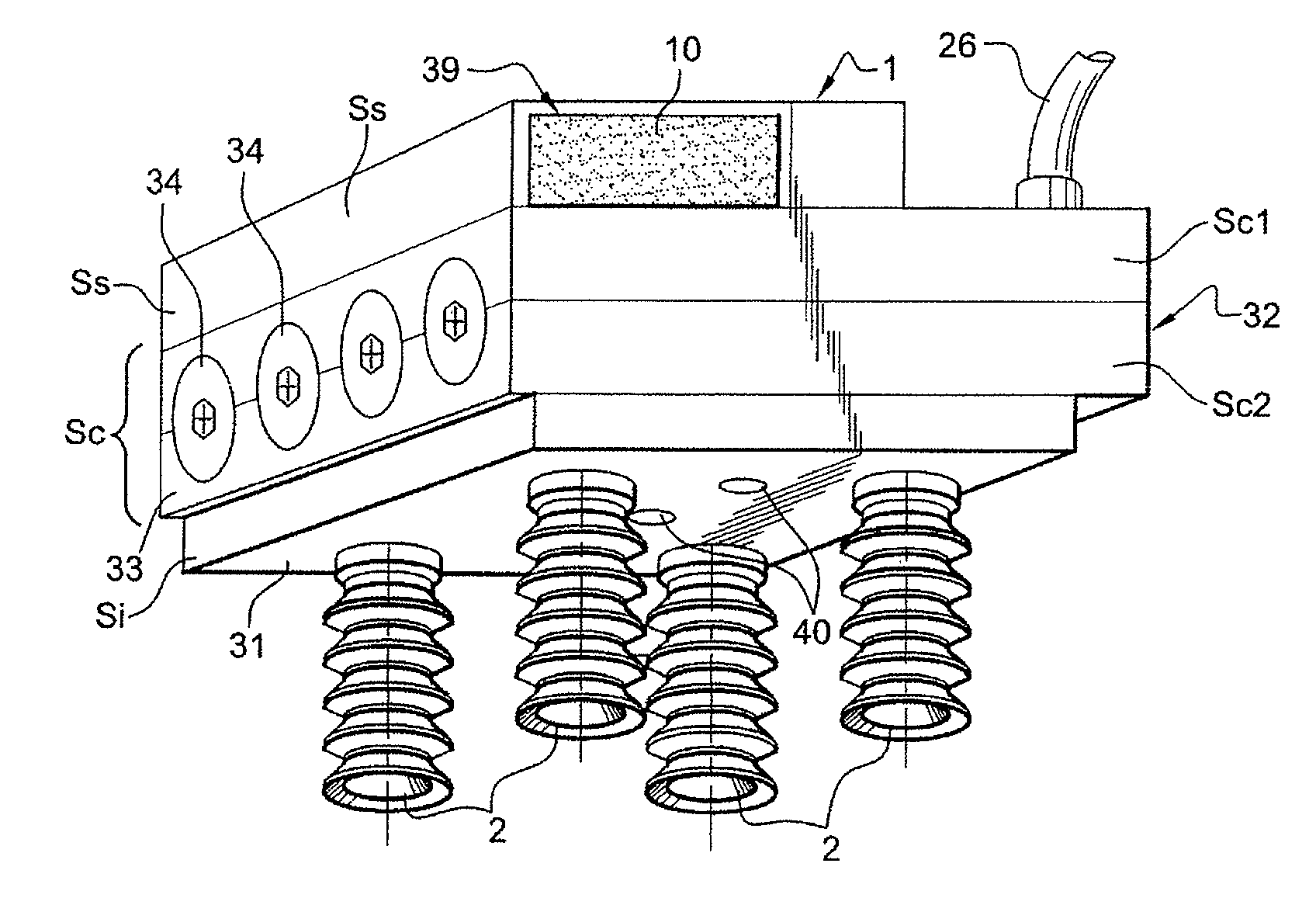
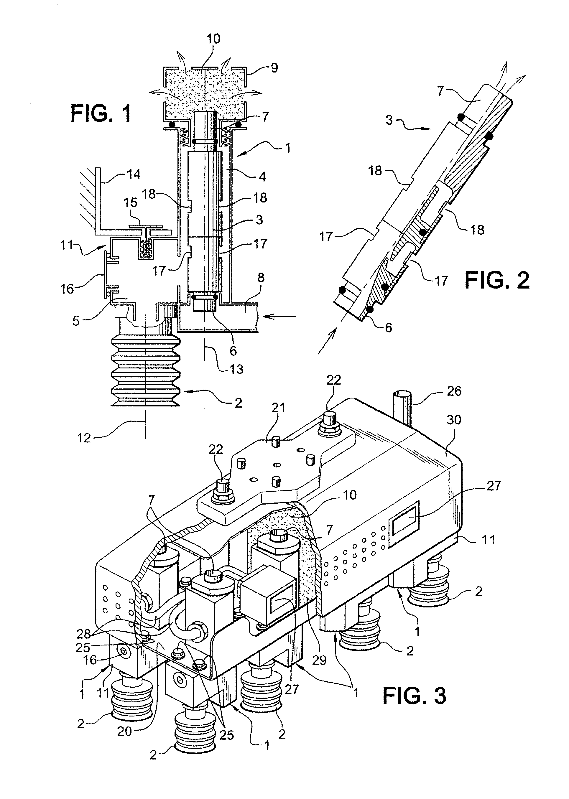
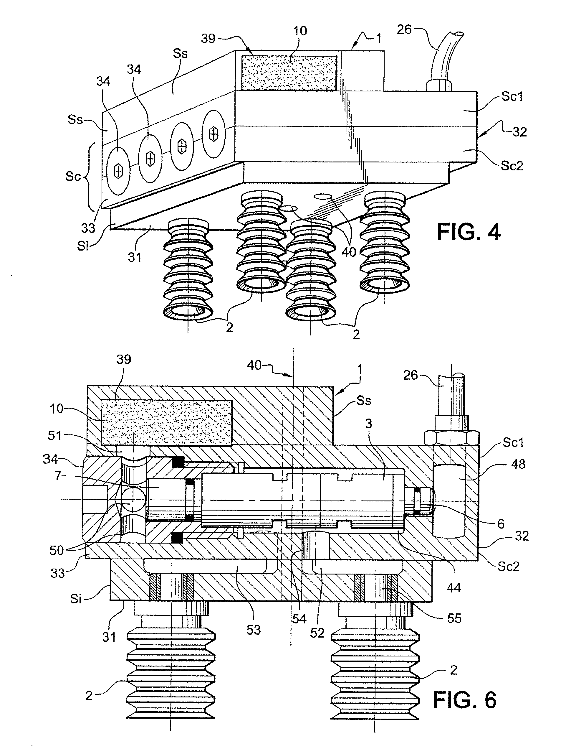
[0038]FIG. 1 depicts tooling that can be qualified as elementary tooling. This tooling comprises:[0039]a body 1 which consists of a compact block of lightweight material, of the thermoplastic or resin type, which block is fashioned by machining and / or by molding and machining,[0040]at least one suction cup 2 which is fixed to said body 1,[0041]a vacuum generator which is in the form of a cartridge 3, and said body comprises bores which place said cartridge 3 and said suction cup 2 in communication.

[0042]These bores on the one hand constitute a vacuum chamber 4 containing the cartridge 3 and on the other hand constitute an ultra-short internal circuit in the form of an orifice or cavity 5 which connects said chamber 4 to said suction cup 2 directly.

[0043]The vacuum chamber 4 extends, in a fluidtight manner by means of the cartridge 3, between the inlet and the outlet of said cartridge 3, which inlet constitutes the mouth 6 and the outlet is in the form of a nozzle 7.

[0044]This mouth ...


PUM


Abstract

The invention relates to a tool that comprises a body (1) in the form of a compact unit made of an appropriate material of the thermoplastic resin material type. The body (1) is adapted for placing the vacuum generator as close as possible to the suction cup (2). It comprises: on the one hand, a bore for housing the vacuum generator in the form of a cartridge (3), wherein said bore defines the vacuum chamber (44) and communicates, on the side corresponding to the inlet of said cartridge (3), with the pressurised air supply, and on the other side, i.e. the side corresponding to the outlet of said cartridge, with an expansion chamber (39) in the form of a silencer; and on the other hand, a very short inner circuit between said vacuum chamber (44) and the suction cup (2), that comprises one or more cavities and/or openings.

Description

FIELD OF THE INVENTION[0001]The present invention relates to holding tooling of the suction cup(s) type associated with a robot for manipulating products with a view to boxing them for example.DESCRIPTION OF THE PRIOR ART[0002]Present-day tooling used on certain product boxing machines consists of a support over which several suction cups are generally distributed and this support is fixed to the end of the arm of a manipulating robot.[0003]The suction cups are connected by flexible pipes to a single vacuum generator situated on the supporting structure of the boxing machine and sometimes on the robot.[0004]Because the tooling is very heavy in relation to the mass of the products that are to be manipulated, such as sachets or pouches for example, present-day robots are over-engineered in relation to the payload that they are to handle.[0005]More “lightweight” robots do exist and these are also generally very high speed but cannot be exploited to the best of their capabilities becaus...

Claims


Application Information

Patent Timeline
IPC IPC(8): B25B11/00
CPCB25J15/0052B25J15/0061B25J15/0616B25J15/0675B65B35/38B65B23/08
Inventor MOUGIN, DIDIER
Owner SIDEL PARTICIPATIONS SAS
Why Eureka
Try Eureka