Apparatus and method for transducing an in vitro or mammalian system with a low-frequency signal

a technology of low-frequency signals, applied in the field of apparatus and method for transducing in vitro or mammalian systems with low-frequency signals, can solve problems such as unknowns

Inactive Publication Date: 2010-09-30
NATIVIS INC
View PDF2 Cites 24 Cited by
  • Summary
  • Abstract
  • Description
  • Claims
  • Application Information

AI Technical Summary

Problems solved by technology

However, what is not known or understood is whether this requirement is related to the actual presence of the effector, or whether it may be due, at least as to certain effector functions, to the presence of energetic modes that are characteristic of the effector.

Method used


Image

  • Apparatus and method for transducing an in vitro or mammalian system with a low-frequency signal
  • Apparatus and method for transducing an in vitro or mammalian system with a low-frequency signal
  • Apparatus and method for transducing an in vitro or mammalian system with a low-frequency signal

Examples


first embodiment

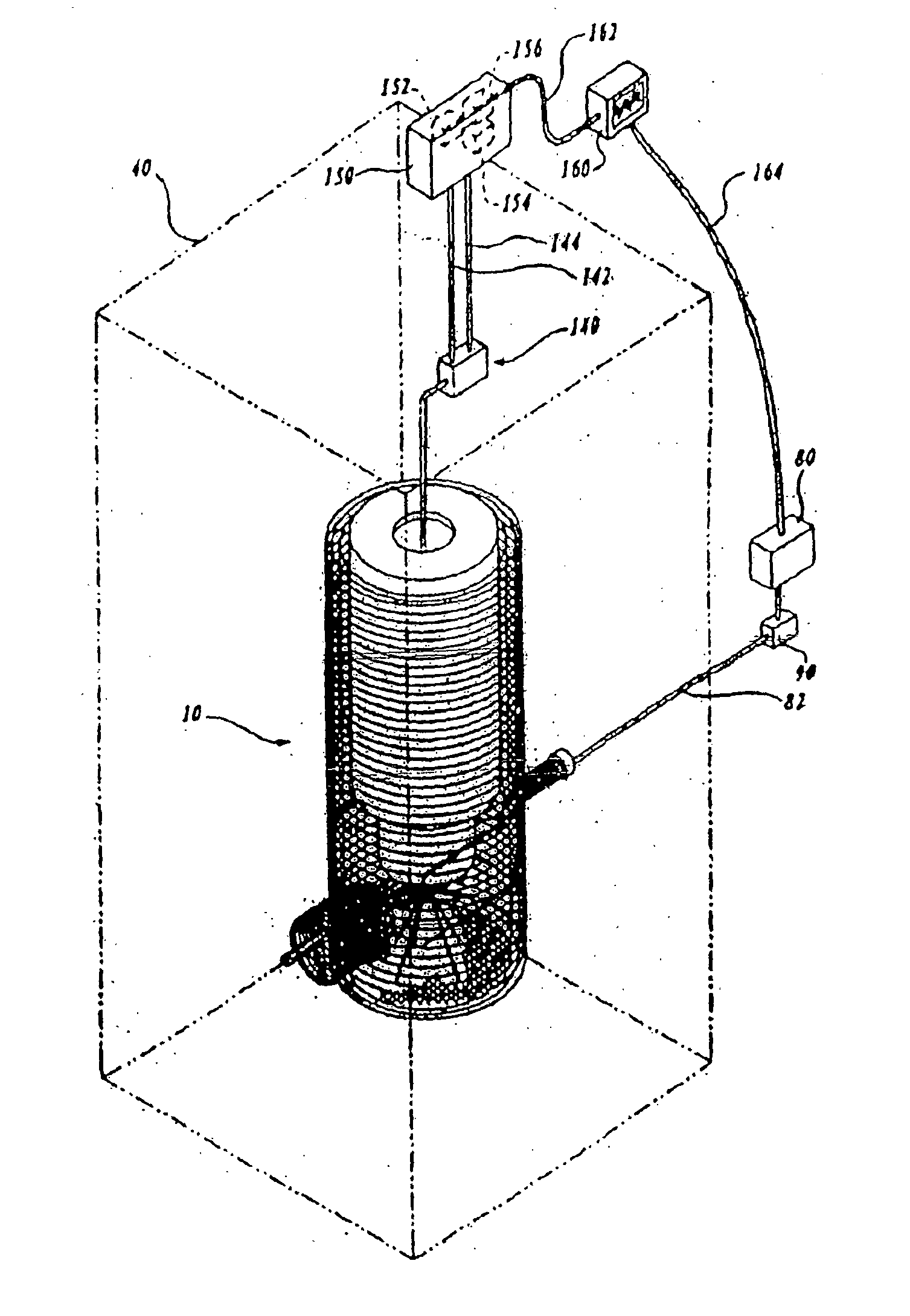
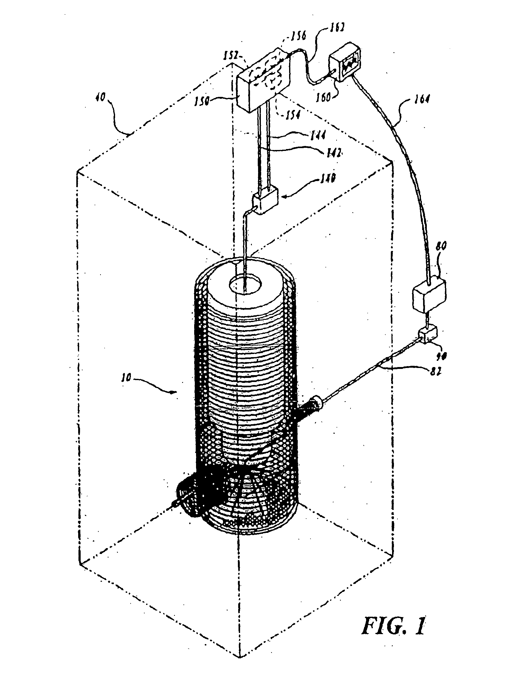
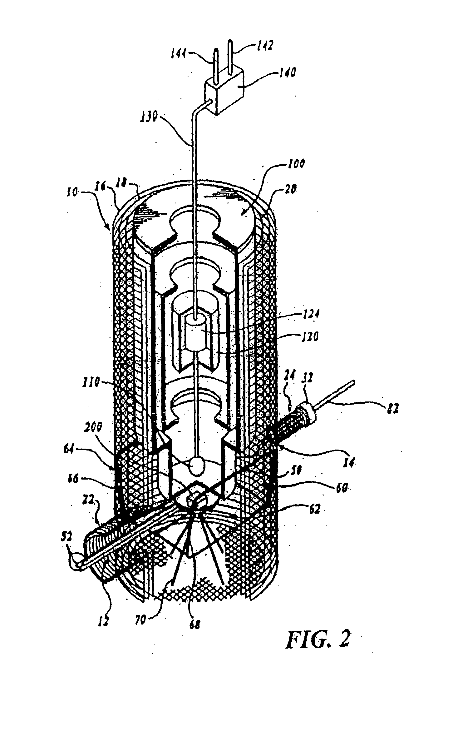
[0126]Referring to FIGS. 1, 2 and 3, a sample of the substance 200 to be measured is placed on the sample tray 50 and the sample tray is placed within the faraday cage 10. In the first embodiment, the Gaussian white noise stimulus generator 80 is used to inject Gaussian white noise stimulus through the Helmholtz transformer 60. The noise signal creates an induced voltage in the gradiometer 110. The induced voltage in the gradiometer 110 is then detected and amplified by the SQUID 120, the output from the SQUID is further amplified by the flux locked loop 140 and sent to the SQUID controller 150, and then sent to the dual trace oscilloscope 160. The dual trace oscilloscope 160 is also used to display the signal generated by Gaussian white noise stimulus generator 80.

[0127]The Gaussian white noise stimulus signal (or other magnetic-field stimulus) is adjusted by altering the output of the stimulus generator 80 and by rotating the Helmholtz transformer 60 around the sample 200, shown i...

second embodiment

[0193]FIG. 11 is a flow diagram of steps carried out in scoring recorded time-domain signals according to this Time-domain signals are sampled, digitized, and filtered as above (box 402), with the gain on the magnetic-field stimulus level set to an initial level, as at 404. A typical time domain signal for a sample compound 402 is autocorrelated, at 408, using a standard autocorrelation algorithm, and the FFT of the autocorrelated function is generated, at 410, using a standard FFT algorithm.

[0194]An FFT plot is scored, at 412, by counting the number of spectral peaks that are statistically greater than the average noise observed in the autocorrelated FFT and the score is calculated at 414. This process is repeated, through steps 416 and 406, until a peak score is recorded, that is, until the score for a given signal begins to decline with increasing noise stimulus gain. The peak score is recorded, at 418, and the program or user selects, from the file of time-domain signals at 422...

third embodiment

[0197]FIG. 12 is a flow diagram of steps carried out in scoring recorded time-domain signals according to this Time-domain signals are sampled, digitized, and filtered as above (box 424), with the gain on the magnetic-field stimulus level set to an initial level, as at 426. The program then generates a series of FFTs for the time domain signal(s) at each noise stimulus gain, at 428, and these plots are averaged at 430. Using the averaged FFT plot, scoring is done by counting the number of spectral peaks that are statistically greater than the average noise observed in the averaged FFT, as at 432, 434. This process is repeated, through the logic of 436 and 437, until a peak score is recorded, that is, until the score for a given signal begins to decline with increasing magnetic-field stimulus gain. The peak score is recorded, at 438, and the program or user selects, from the file of time-domain signals at 442, the signal corresponding to the peak score (box 440).

[0198]As above, this...


PUM

PropertyMeasurementUnit
magnetic fieldaaaaaaaaaa
frequencyaaaaaaaaaa

Abstract

Method and apparatus for generating and selecting low-frequency time-domain signals capable of transducing a mammalian system, to produce an agent-specific effect on the system, are disclosed. Low-frequency time-domain signals are generated in the presence of an injected magnetic stimulus, and the resulting signals are selected by a scoring algorithm, and optionally, by testing each signal identified by the scoring algorithm for its ability to produce an agent-specific response in a in vitro system containing components that are responsive to the agent. The selected signals are used to transduce the mammalian system by applying the signals to an electromagnetic transduction coil that holds the sample.

Description

FIELD OF THE INVENTION[0001]The present invention relate to signals readable by a system for converting or transducing the signal into electromagnetic waves, and to methods of producing and applying such signals.BACKGROUND OF THE INVENTION[0002]One of the accepted paradigms in the fields of chemistry and biochemistry is that chemical or biochemical effector agents, e.g., molecules, interact with target systems through various physicochemical forces, such as ionic, charge, or dispersion forces or through the cleavage or formation of covalent or charge-induced bonds. These forces may involve energy modes in either the effector agent or target system.[0003]A corollary of this paradigm is the requirement, in effector-target systems, of the effector agent in the target environment. However, what is not known or understood is whether this requirement is related to the actual presence of the effector, or whether it may be due, at least as to certain effector functions, to the presence of e...

Claims


Application Information

Patent Timeline
Patent Type & Authority Applications(United States)
IPC IPC(8): G01N27/72
CPCG01N37/005G01N27/72C12M1/42G01N33/48
Inventor ATWOOD, CHRISTOPHER G.BUTTERS, BENNETT MICHAELBUTTERS, JOHN T.MARFATIA, SHIRIN M.VOGELI, GABRIEL
Owner NATIVIS INC
Why Eureka
Try Eureka