Magnetic resonance imaging apparatus and method

Active Publication Date: 2010-09-30
HITACHI LTD
View PDF3 Cites 24 Cited by
  • Summary
  • Abstract
  • Description
  • Claims
  • Application Information

AI Technical Summary

Benefits of technology

[0009]The object of the present invention, in the imaging technique for imaging a wide range of an object while moving a table, is to provide an MRI apparatus and meth

Problems solved by technology

In this case, in order to obtain high-quality images by the above-described shimming process, many steps are required since i

Method used


Image

  • Magnetic resonance imaging apparatus and method
  • Magnetic resonance imaging apparatus and method
  • Magnetic resonance imaging apparatus and method

Examples


embodiment 1

[0042]Next, the MRI apparatus and method of the embodiment 1 will be described in concrete form.

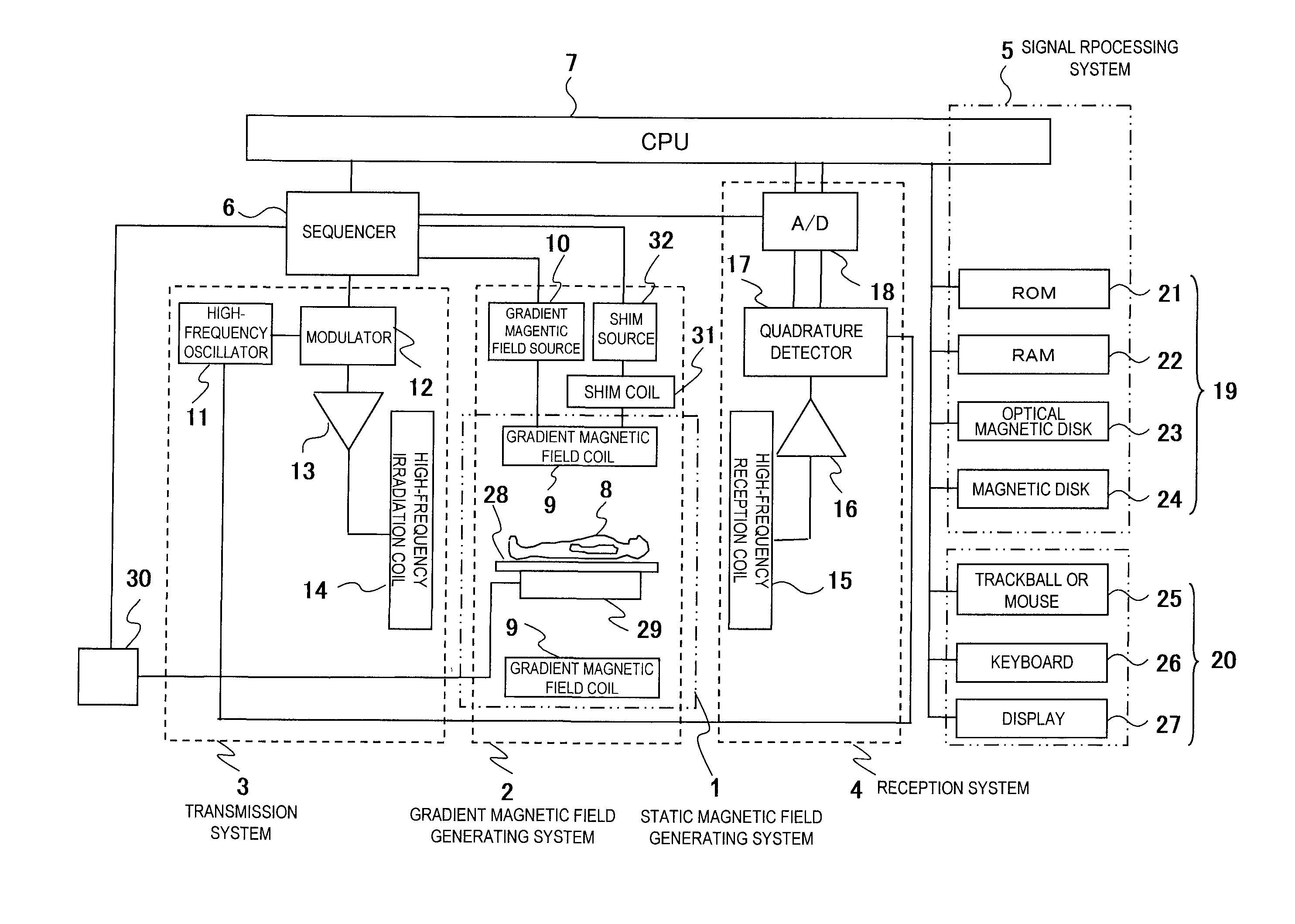
[0043]The MRI apparatus related to the embodiment 1 of the present embodiment in FIG. 1 further comprises a table control system. The table control system comprises a table 28 on which an object is placed, a table moving mechanism 29 which is installed parallel to the table 28 for moving the table 28 in the respective 3-dimensional directions, and a table control unit 30 for controlling the table movement in connection with the pulse sequence by the control of the sequencer 6 or the CPU 7. The table moving mechanism 29 is connected to the table control unit 30, and the table control unit 30 is connected to the sequencer 6. Also, the table moving mechanism 29 comprises a position detecting unit (not shown in the diagram) for detecting the position of the table 28. The table control unit 30 controls the movement of the table 28 using the positional information from the position detecting un...

embodiment 2

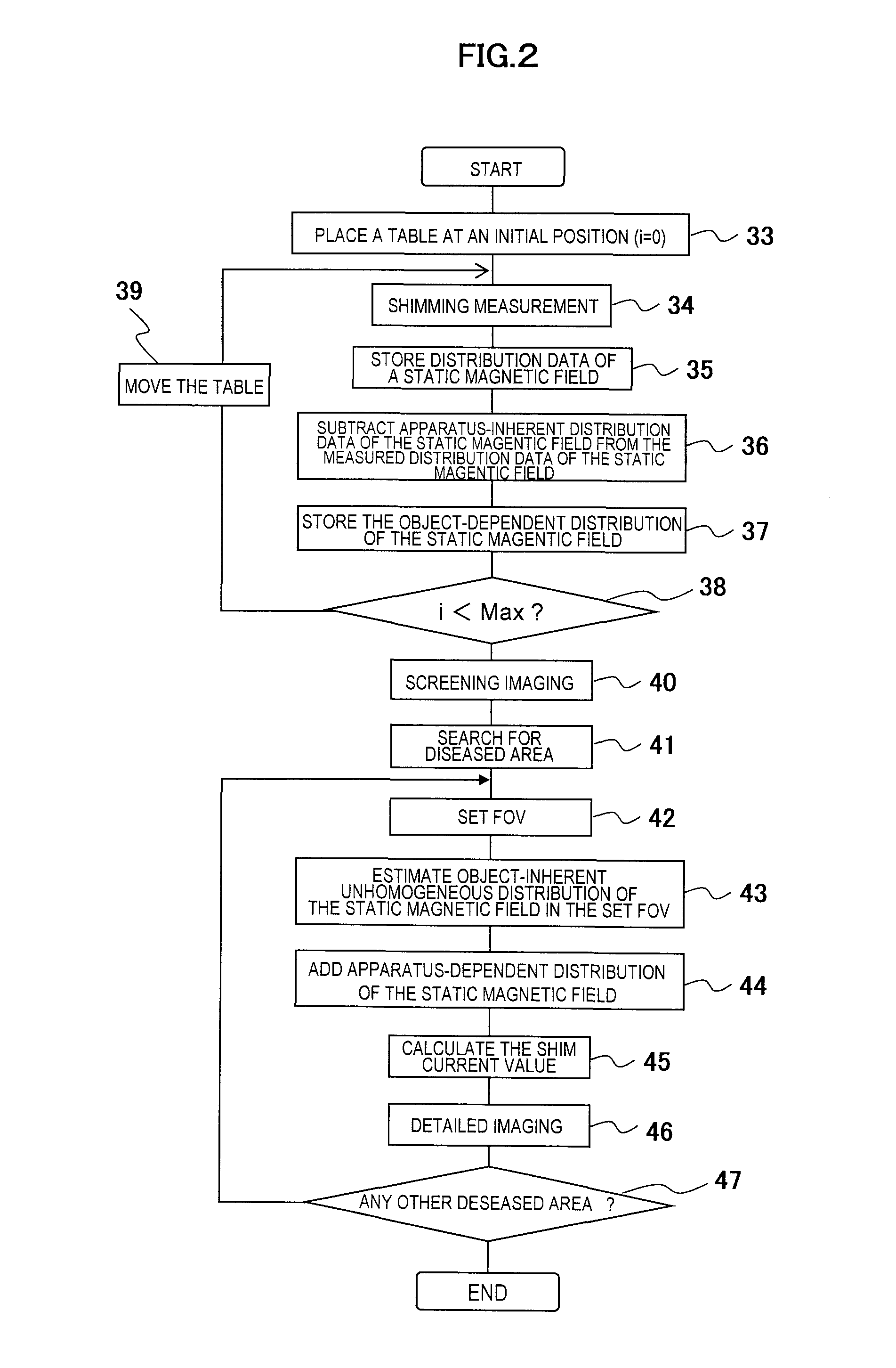
[0081]Next, the concrete configuration of the MRI apparatus and method in embodiment 2 will be described. The present embodiment is an example of the case that the table is to be moved continuously. FIG. 6 is a flow chart showing the operation in the embodiment 2 of the MRI apparatus related to the present invention. In this embodiment, the steps of shimming measurement from step 33 to step 39 are the same as the embodiment 1, and only the steps of the present imaging are different.

[0082]In the present embodiment, as shown in the schematic diagram of the imaging in FIG. 7, the imaging is executed while continuously moving the object with respect to the imaging FOV from the head part toward the feet. The imaging sequence used in the present imaging is arbitrarily determined in accordance with the objective of examination and not limited in any specific way. In the example shown in FIG. 7(a) of the present embodiment however, the direction for reading out the signals is the moving dir...

embodiment 3

[0099]Next, concrete configuration of the MRI apparatus and method in embodiment 3 will be described. The imaging steps in the present embodiment are similar as the embodiments 1 and 2, and only the only difference is the steps for shimming measurement. In the present embodiment, in order to obtain the object-dependent inhomogeneous distribution of the static magnetic field and the apparatus-inherent inhomogeneous distribution of the static magnetic field, two inhomogeneous distributions of the static magnetic field that are obtained when the gantry is placed in two positions in the vicinity of the object are used. FIG. 8 is a flow chart showing the operation of the embodiment 3 of the MRI apparatus related to the present invention, and FIG. 9 is a schematic diagram of the shimming measurement in embodiment 3. The procedures thereof will be described below.

[0100](Step 69)

[0101]First, static magnetic field distribution is measured at an arbitrary position as shown in FIG. 9(a) (for e...


PUM


Abstract

A magnetic resonance imaging apparatus comprising static magnetic field generating means for generating a static magnetic field in an imaging space, measuring means for generating a high-frequency magnetic field and a gradient magnetic field in the imaging space and measuring a nuclear magnetic resonance signal generated from an object to be examined placed in the imaging space, signal processing means for reconstructing a magnetic resonance image according to the nuclear magnetic resonance signal, control means for controlling the measuring means and the signal processing means, and display means for displaying the reconstructed magnetic resonance image obtained by the signal processing means.
The magnetic resonance imaging apparatus further comprises storing means for storing a first set of information representing an inhomogeneous distribution of the static magnetic field generated depending on the characteristic of the static magnetic field generating means and a second set of information representing an inhomogeneous distribution of the static magnetic field generated depending on the tissue of the object, setting means for setting a field of view for imaging in a desired region of the object, selecting means for selecting information corresponding to the set field of view for imaging out of the second set of information as a third set of information, and correcting magnetic field generating means for generating a correcting magnetic field according to the third set of information and the first set of the information.

Description

TECHNICAL FIELD[0001]The present invention is related to a magnetic resonance imaging (hereinafter referred to as MRI) apparatus and method, particularly to a technique capable of improving correction of inhomogeneous distribution of the static magnetic field in a method for imaging a wide range of region while moving a table.BACKGROUND ART[0002]An MRI apparatus is, when electromagnetic waves are irradiated to an object to be examined placed in a homogeneous static magnetic field, for obtaining a magnetic resonance image (hereinafter referred to as MRI) that represents the physical description of the object by detecting a nuclear magnetic resonance signal (hereinafter referred to as an NMR signal) using NMR phenomenon generated in atomic nuclei of an atom by which the object is constituted and reconstructing an image using the NMR signal.[0003]In MRI, a technique is commonly known for imaging a wide range or whole body of an object while moving a table on which the object is placed ...

Claims


Application Information

Patent Timeline
IPC IPC(8): G01R33/48
CPCA61B5/055G01R33/243G01R33/543G01R33/58G01R33/56383G01R33/56563G01R33/56375A61B5/704
Inventor ABE, TAKAYUKITAKAHASHI, TETSUHIKO
Owner HITACHI LTD
Why Eureka
Try Eureka