
Amplifier circuit

a technology of amplifier circuit and amplifier, applied in the field of amplifier circuit, can solve the problems of speaker to produce a deficient sound, artificial distortion and offensive sound, and achieve the effect of adequate power and reliable prevention of clipping

Active Publication Date: 2010-09-30
YAMAHA CORP
View PDF3 Cites 2 Cited by
  • Summary
  • Abstract
  • Description
  • Claims
  • Application Information

AI Technical Summary

Benefits of technology

[0011]It is an object of the present invention to provide an amplifier circuit which prevents clipping from occurring in the waveform of an output signal while maintaining power and dynamics.
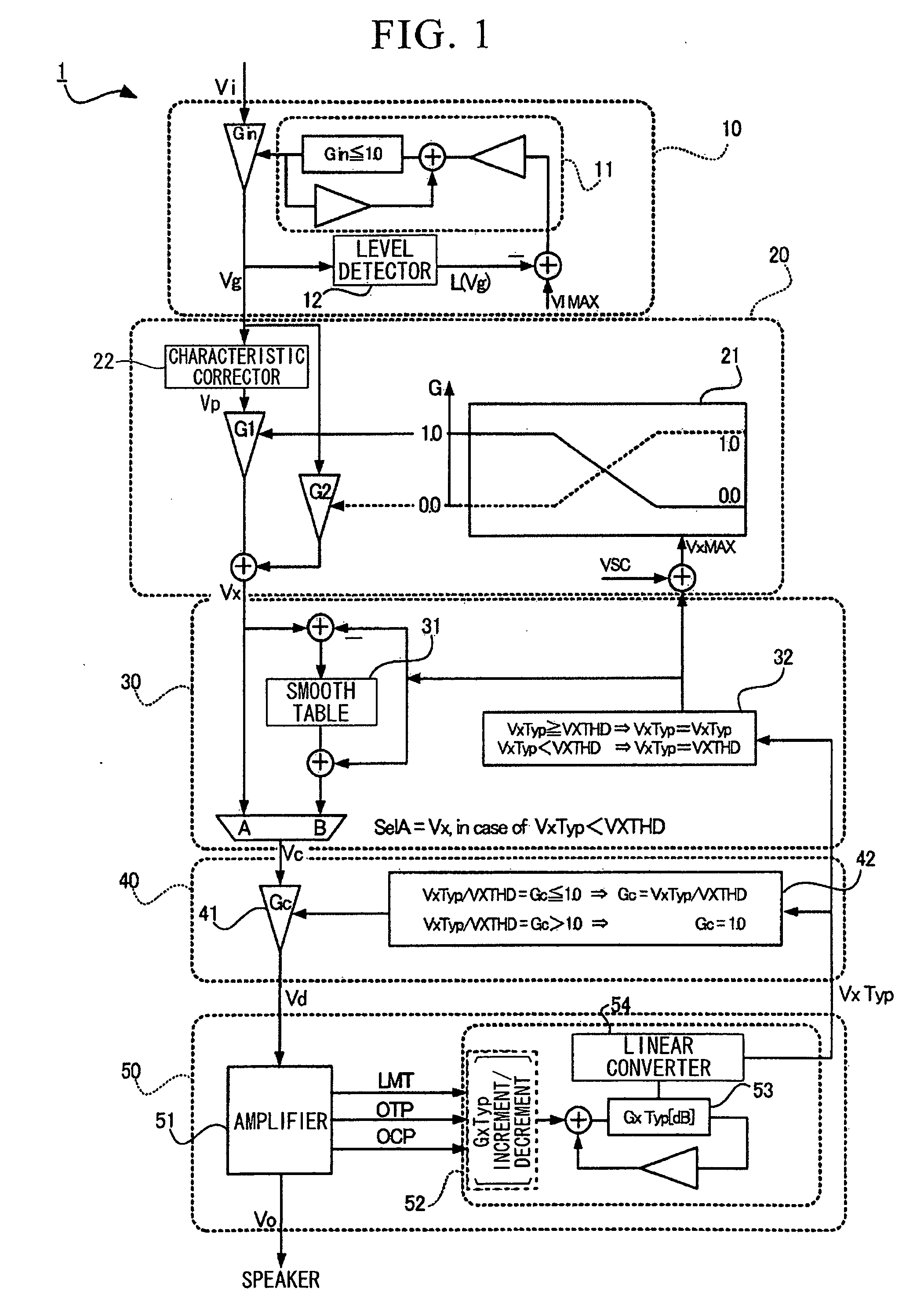
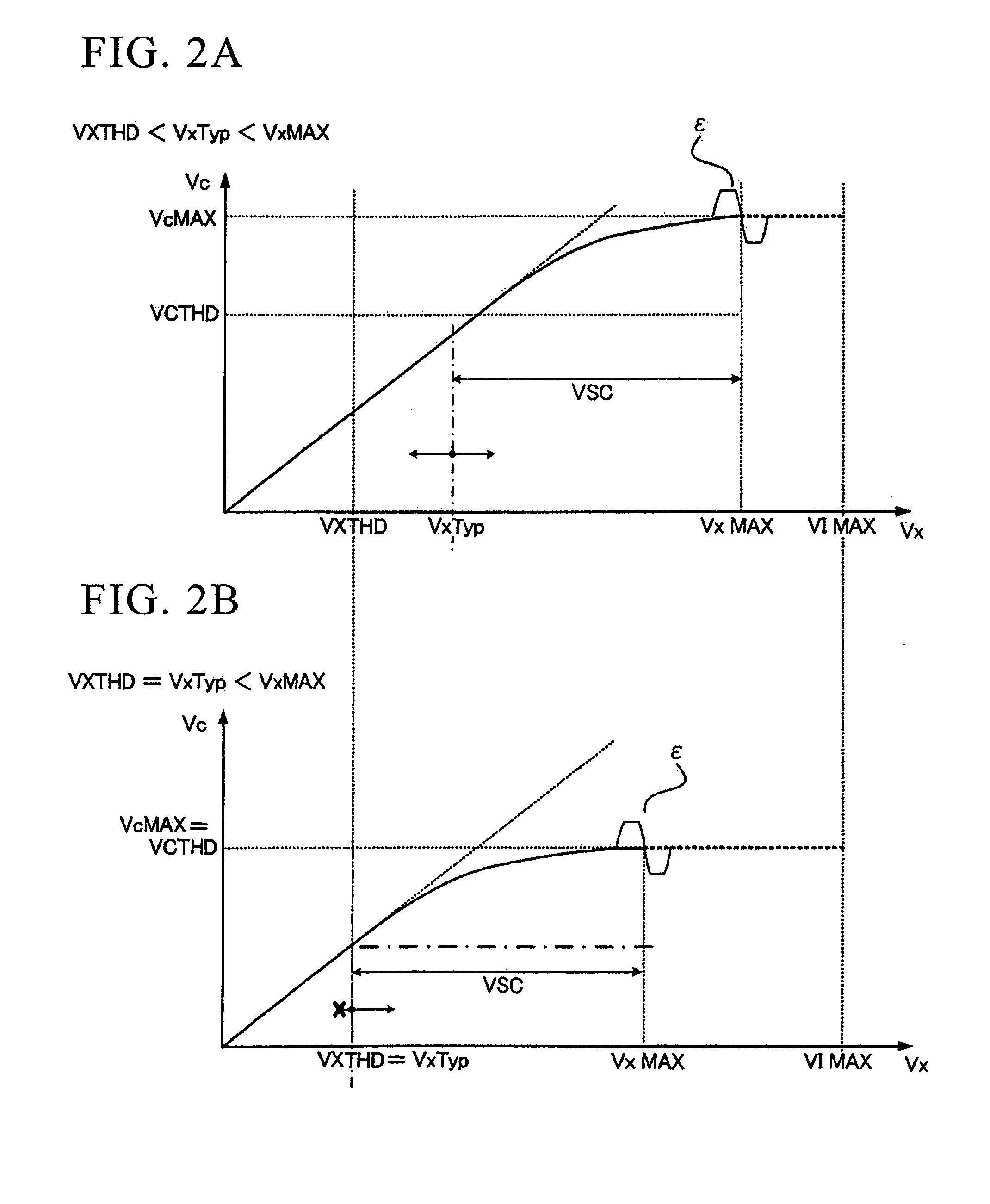
[0014]In the smooth curvilinear process, the second conversion signal is gradually and smoothly varied in level along with the smooth curvilinear relationship. Compared with the linear proportional relationship in which the third conversion signal increases in linear proportion with the second conversion signal, the present invention suppresses the increase rate of the third conversion signal by way of the smooth curvilinear relationship. The linear proportional relationship is advantageous in that it can prevent clipping from occurring in the waveform of the output signal, while the smooth curvilinear relationship is advantageous in that it can maintain an adequate power in the output signal. For this reason, the present invention changes the processing in response to the state variable of amplification (VxTyp), which is compared to a default value (VXTHD). Specifically, the smooth curvilinear process is performed when VxTyp≧VXTHD, while the gain decrement process is performed when VxTyp<VXTHD.
[0016]Thus, it is possible to reliably prevent clipping from occurring in the output signal while maintaining an adequate power in the output signal.

Problems solved by technology

Upon receipt of an output signal having a clipped level from an amplifier circuit, a speaker (serving as an electric load) may produce an artificially-distorted and offensive sound.
However, the above measures bring a decline in the level of an output signal of an amplifier circuit, thus causing a speaker to produce a deficient sound lacking power and dynamics.

Method used


Image

  • Amplifier circuit
  • Amplifier circuit
  • Amplifier circuit

Examples


Embodiment Construction

[0027]The present invention will be described in further detail by way of examples with reference to the accompanying drawings. In this connection, these drawings do not necessarily reflect the accurate dimensions and factors in designing the circuitry.

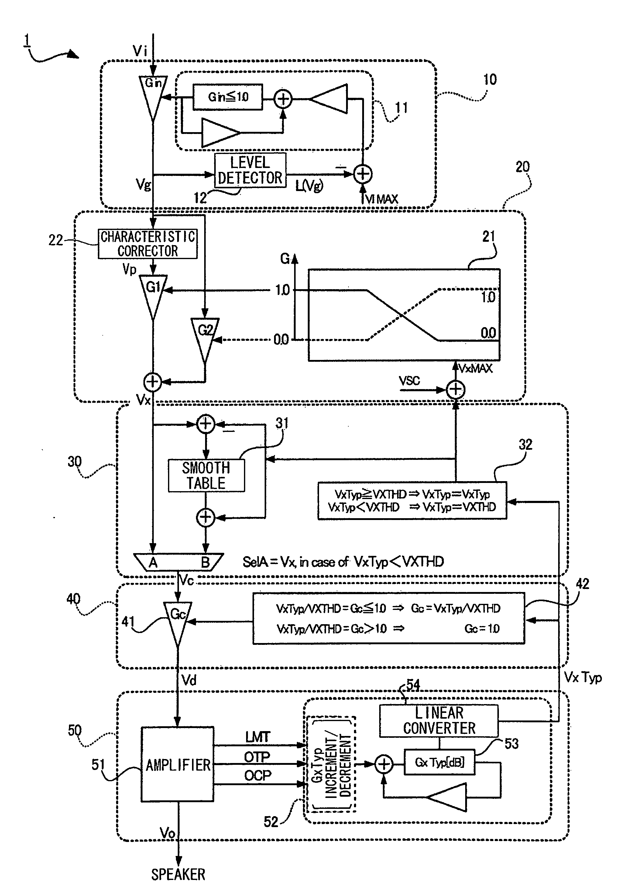
[0028]FIG. 1 is a block diagram of an amplifier circuit 1 according to a preferred embodiment of the present invention. The amplifier circuit 1 is constituted of a first gain correction unit 10, a characteristic correction unit 20, a smooth curvilinear correction unit 30, a second gain correction unit 40, and an amplification unit 50.

[0029]The first gain correction unit 10 includes a low-pass filter (LPF) 11 and a level detector 12. The first gain correction unit 10 transmits an input signal Vi toward the characteristic correction unit 20. Herein, the first gain correction unit 10 converts the input signal Vi into a first conversion signal Vg while fixing the maximum value of the first conversion signal Vg to the predetermined value.

[...


PUM


Abstract

An amplifier circuit performs a characteristic correction process and a smooth curvilinear process on an input signal before being subjected to amplification. The characteristic correction process is a frequency characteristic process, which is performed on the input signal so as to produce a processed signal (Vp). Either the input signal or the processed signal, or the mixture of these signals is subjected to the smooth curvilinear process whose start point is designated by a state variation of amplification (VxTyp). Alternatively it is subjected to a gain decrement process instead of the smooth curvilinear process when the state variation of amplification is less than a default value (VxTHD). Thus, it is possible to prevent clipping from occurring in the amplified output signal while maintaining an adequate power.

Description

BACKGROUND OF THE INVENTION[0001]1. Field of the Invention[0002]The present invention relates to amplifier circuits such as power amplifiers adapted to audio devices.[0003]The present application claims priority on Japanese Patent Application No. 2009-79463, the content of which is incorporated herein by reference.[0004]2. Description of the Related Art[0005]Conventionally, amplifier circuits have been used to drive electric loads (e.g. speakers) in response to input signals (e.g. audio signals). When the level of an input signal exceeds a predetermined range of amplitude, an amplifier circuit is subjected to clipping with respect to the waveform of an output signal. Upon receipt of an output signal having a clipped level from an amplifier circuit, a speaker (serving as an electric load) may produce an artificially-distorted and offensive sound. For this reason, it is necessary to prevent clipping from occurring in waveforms of amplified signals.[0006]Various types of amplifier circ...

Claims


Application Information

Patent Timeline
IPC IPC(8): H03G3/20
CPCH03G9/18
Inventor MORISHIMA, MORITO
Owner YAMAHA CORP
Learn More